Malfunctions of matrixes of LCD TVs and their elimination. How to fix and repair PHILIPS LCD TV yourself at home. The main causes of malfunctions and self-diagnosis of malfunctions of modern LCD and LED TVs
1550.) PHILIPS 25GR5765 / 22B G110 1). on the lamp (with the OS line disabled), the PSU is started and instead of 148v only 60-80v are available and is not regulated, if the oscilloscope probe is placed on the base of the TP7652, the voltage at the PSU output rises to normal, replace the conder on the 1m С2645 optocoupler. (1-pin on GND)
2). on the lamp (with the OS line turned off), the PSU starts (that is, the lamp lights up and goes out) transition to protection by disconnecting R3502 8k2 from 148v - the PSU on the lamp starts, check tp7591 for a breakdown (located in the TDKS area down to the tuner to the right of the trance).
3). The protection of the power supply is collected on tr 7658 (7656) and tr 7655 in operating mode on the anode of the zener diode 6657 LLZ-C20 should be 0v constant and the presence of line pulses, if there is a voltage of 3-5v, the transition to protection and the voltage at the output of the PSU 15-20v. (dezh mode in the slave state 31v). To test the PSU’s performance, the resistance 3660 5k8 going to the TP7655 base and the TP7658 collector can be turned off (thus we turn off the protection of the PSU), turn on the TV and go along the path to the circuit to search for 3-5v.
four). the output BUT18 tr PSU will fly out after an hour of operation, two or three days in different ways, a periodic break of the t7654 in the secondary circuit (the collector through R 220 Ohm to 2-pin optocouplers) can be replaced by BC547
1551.) PHILIPS 28GR5701 / 02Z G110-2 (banan) vertical linearity is violated (top is stretched, bottom is squeezed); check with parallel connection C2509 2.2 / 50v (near TDKS). Or by replacing the C2508 470.0 / 35v.
1552.) PHILIPS 25GR9760 / 02B G110-2 (banan) underestimated output B + to 50; check when dismantling 7612 BC858 smd (for leakage).
1553.) PHILIPS 25PT4511 / 22 Chassis MD1.1E raster OK, OSD - OK, the screen is dark, there is sound, there is no image - check for the presence on the PC (smd) TR7390 base 9v1, emitter 12v, if not check R3450 68kOhm soldering is located on the main Chassis near TDKS right side.
1554.) PHILIPS 27CE4298 / 02R schass 2B (R3619 \u003d 56 Ohm, R3620 \u003d 56 Ohm) often in a cliff.
1555.) PHILIPS 25ST2451 / 02B GR2.2 OSD - OK, the screen is dark, there is no sound, check the power + 12v on the 13-pin TDA2549 (open resistor jumper).
1556.) PHILIPS 28ST2471 / 02B GR2.2 AA on the start lamp - OK. the diode blinks 4 or 5 times - check on the collector of the output lowercase the presence of B + 150v. the raster is narrowed at the top with green. with ОХ lines, check by parallel connection С2502 47.0 / 50v.
1557.) PHILIPS 37ZZ3223 / 22B chassys ANUBIS A no start, TV pulsates (protection works). Disconnect the line, connect the lamp to the load - the PSU starts, on the lamp 110V (not adjustable). Connect the line, hang up terminal 4 of the TDKS (power supply of the circuit + 5V) into the air, the TV starts, the control circuit is V + 95v faulty, check 3537 (BC846, smd) R3551 150 Ohm (smd), 7552 BC327. horizontal strip on the screen - check by replacing the capacitor 3504 220n between pins 3 and 7. after turning on the TV, flashing 1 on the screen, then highlight S1 and highlight F2 on the bottom of the raster - memory 24С02 is faulty. the image is dominated by red-synm, there is a green OSD, but there is no G in the RGB signal on the PC - the TDA3504 is faulty. meter channels OK, in the DMV range there is snow and the absence of 22 channels - the tuner is faulty.
1609.) Philips 32PW9763 / 58 and others. Chassis MD2.21E, 2.22E, 2.23E TV after switching on (Picture appears for a moment) after 10-15 seconds. turns off, the LED on the front panel starts to blink red quickly. TVs 2pcs. The external manifestations are the same and the same, only the second is turned off at large intervals and sometimes can work for quite a while. Everything turned out to be quite simple, in the first case, do not break the line isolation transformer (TMS), in the second, again, do not break the connector on board A (raster correction), it is easy to find it, it looks like latin letter U stands on large signal board.
1627.) PHILIPS 14PT1352 / 00 PSU beeps (even with disconnected loads), the output springs are almost zero. Guilty C2501 (leak).
1732.) Philips 14CE1200 according to the owner: it turned on, then no, and now it completely stopped turning on. I was amazed when I read in the tips about faulty chokes in the Philips, but after digging for two days, I just began to close all the chokes with tweezers in a row and click the switch and, lo and behold, when 5697 (between two C 47.0x160) was closed, the TV turned on. Put another L - does not turn on. I just had to put a jumper .. The jitter of the image at the top of the screen was due to drying From 2098 about m / s of the pulse generator.
1759.) Philips 21GX54A arrived with a broken TA8403K frame scan chip. Checked the power line turned out to be normal. Installed a new chip and when turned on, it immediately burned out. Checked the whole harness. In place of R323 2.2 Om installed to protect 100 Ohms disconnected the frame coils when turned on, the new microcircuit did not burn out. Connected frame coils. At pin 2 of the chip, a highly distorted signal. I changed the deflection system, returned R323 to the norm of 2.2 Ohms. Personnel earned normally. It turned out in the old OS in the frame coils inter-turn circuit.
1762.) Philips 29 PT9007 / 58 (Shassis EM2E) Fault: when the network button is turned on, a horizontal scan is heard, a briefly high voltage appears. The raster does not appear, protection is activated and the LED on the front of the TV starts blinking at a frequency of 3 Hz (3 times per second). The protection was turned off by soldering the zener diode 6405 BZM55-C39 (type SMD). The TV started up, the raster correction by lines is violated. We entered the service menu: for what we pressed on the remote control 062596 and pressed (i +) and reset the error buffer. We tried to adjust the size of the raster horizontally, the raster remains large, there is no adjustment. A dangling resistor 3483 was found according to the 1K circuit, in fact, 100 ohms were installed. The raster began to adjust. Soldered instead of a zener diode 6405, protection again worked. Again the zener diode was unsoldered and went into the service menu - error 005 is indicated in the buffer. The service instruction indicates a problem with the power supply of +8 volts. We checked the supply voltage of 5 volts and 8 volts - the norm. (check leg 105 (+8), 106 (+5) on the OTC processor. The culprit of all ills is a capacitor 2495 100n (type SMD).
1785.) PHILIPS-21PT136B / 58. Fault: It turns on from standby mode, the LED on the front of the TV responds to commands from the remote control. No sound or image. The voltage at terminal 36 of the TDA8362E — line scan — is overstated. Replace the chip.
1851.) Philips 28GR6780 Problem: There is no image, the screen is filled with milk. When a breakdown occurred, there was a burning smell. A burned-out R3331 \u003d 1 ohm was visually detected. It is installed in the power circuit of the video input switch.
1853.) Philips 28GR6780 Fault: Tuner band switch control pins punched. The remaining functions of the processor TMP47C634N-R364 fulfills properly. Finding such a processor is extremely difficult. Repair option in case of failure of some microprocessor functions. The processor is controlled by the RC-5 remote control. An additional, standard MDU on the EKR1568VG1 was connected to the TV (understands the same remote control). Range switching is done by him. The module is powered by a TV. The inconvenience in setting up channels - but this is a trifle. Thus, the modified TV is in operation for more than a year.
1855.) Philips 28GR6780 Fault: Periodically narrowing the raster horizontally. Replacing the BD236 transistor in the size adjustment circuit (it is mounted on the radiator). Fits KT837V.
1890.) Philips 28GR6780 Fault: no frame scan. After eliminating the non-contact on the connector of the deflecting system - in the image above the screen - “accordion”. The reason for the non-VKontakte resistor chip is 150 ohms. It is installed next to the connector, parallel to the frame OS.
1928.) Philips 28GR6781. No general sync. Flickering image. On different channels, in different ways. After warming up, it can work normally. Replacing a power capacitor TDA2579A (10 pin)
1943.) PHILIPS 14PT138A / 58R (L7.1A AA chassis) Distorted, faint sound. There is no sound from the bass input. The reason is the internal msc.TDA8362E internal circuit is faulty between pins 1 and 50 (TV / AV switch - adjustable amplifier). If the LF input is not used, then you can eliminate the defect by throwing the input UMZCH (C2120) with pin. 50 TDA8362E on pin 1 (unregulated amplifier output) TDA8362E.
1953.) PHILIPS-21PT136B / 58. There is sound, there is glow, the screen is dark. Twisting the accelerating result does not. The voltages at the cathodes are 30–40V (i.e., the tube is not blocked along the cathodes). The check shows the absence of accelerating voltage on pin 7 (G2) of the kinescope panel. TDKS? But when the wire accelerating from the board of the kin is torn off, the voltage appears. The conclusion is "replanting." We measure the resistance of pin 7 relative to the "ground" of the PC and get 2.5kOhm! We remove the PC from the pipe - the circuit disappears. The test shows the interelectrode closure of the terminals 7 (G2) and 5 (G1) of the kinescope (mutual resistance is about 1 kΩ), and pin 5 (G1) sits on the PC ground through R3279 (1.5 kΩ) on the PC. Hence the desired 2.5kOhm! With the separation of 3279 from the "earth" and soldering accele. wires in place we get a distorted, blurry image with LOCH. It was possible to eliminate the interelectrode and restore the normal working capacity of the pipe by the following method: 1. Put 3279 in place. 2. put a jumper on the pin. glow; 3. tear off the wire accele. from PC; 4. pull the focus wire out of the kin panel; 5. On TV, 3-4 times touch for a few seconds. focus wire pin. 5 kinescope sockets. After this operation, the performance of the tube completely restored.
2028.) PHILIPS 33CE536 / 30R Chasiss 3A Fault: first, when you turn on the TV, the bottom of the raster twitches, then it shrinks to the middle, after a few seconds the raster took on its normal size and the TV could not work as predictably as the appearance of this defect was not predictable again. The cause of this malfunction was a “floating” open circuit of the 2582 capacitor connected to the 22 legs of the TDA8432 microcircuit to the case. This capacitor is responsible for the vertical size.
2062.) PHILIPS 14GR1221 / 59R From the words of the owner, it periodically turned off randomly, then completely stopped turning on. The C3795 crashed - replaced with our KT8108, the device worked, but an arbitrary shutdown was repeated. When checking 103.5 V, the voltage is normal, but if the voltage is set to 103.0 V, the defect disappears (apparently the F2D thyristor is very sensitive to small voltage changes).
2074.) Philips 14GR1221 / 59R Fault: The line scan is in start-stop mode, or this defect appears with heating. If you turn the tuning resistor AGC against the hour. arrows, the TV starts to work normally (for a while). The reason is the breakdown of the capacitor 2021 (22nF).
2075.) Philips 25PT5207 / 60 Fault: It does not turn on from standby mode (line and frame start and turn off into standby mode after 5-8 seconds). The foot of the capacitor 2493 (near the base of the horizontal transistor) is torn off, so protection by E / W correction is triggered.
2076.) Philips 25PT5324 / 58 chassis A8.0 Fault: It does not turn on from standby mode, the LED starts blinking after a short start of horizontal scanning. Reason: do not get one leg of the transformer on the raster correction board. You also need to solder the first leg of the connector on the deflecting system (Philips OS disease).
2077.) Philips 14PT1345 chassis L9.2 Fault: According to the client, the device after a thunderstorm. Initially, the SR did not start, after replacing the pre-output transistor, the SR tries to start (the LED blinks). If the TV is forcibly switched on to the operating mode (unsolder 19n. Percent), then the SR starts up; a raster appears slightly reduced horizontally and vertically only the upper half. By measuring the frequency of starting imp. SR got something around 20kHz. Replacing the video processor, staffing did not help. It turned out that at the time of start, the SR start pulse is generated by ms 7607 NE555D, and after the start of the SR, 8842 starts working. After long torment, the TV started working after replacing the 2651 100uF / 25V capacitor (according to 10uF) and soldering the 7620 transistor and 6612 zener diode.
2078.) Philips 25PT4103_60 chassis L6.2 Malfunction: With heating, the horizontal size decreases, the picture begins to relax. Power supply 130V instead of 150V. The reason is the loss of capacitance 2515 100uF / 160V.
2086.) PHILIPS-14GX8512 after replacing the TDKS, TDA8362, TDA3653V, the LED on the front panel blinks, replacing 6474 (zener diode 5.1v).
2091.) PHILIPS 28GR770 / 22B Malfunction: the TV does not turn on, at the output of the power supply instead of 145v (50v). After installing a jumper between the base and the emitter of the horizontal transistor, 145v appeared, the replacement of the TDKS 37554 is required.
2114.) PHILIPS 14PT1345 Chassis L9.2E AA. Processor SAA5542PS / M4 / 0270. Fault: there is no image, there is sound. When checking the power supply voltage is normal, there is a glow, high and accelerating voltage is normal. Suspicion fell on the TDA8842S video processor. Replacing this chip has not changed anything. The flash memory of the 24C08 was checked, but even this did not work. Remaining personnel. After replacing the TDA9302H chip, the TV worked fine.
2148.) PHILIPS 21PT133A / 58R Malfunction: the TV does not turn on, the LED on the front panel blinks constantly. Sometimes the TV can start for 10 - 15 seconds and turns off again and the LED blinks. Faulty transistor 7219 BC338. The tester shows that the transistor is working.
2162.) Philips 21PT136B / 58 Malfunction: when you turn on the image, lines are knocked out, after a minute it sews specifically for all signs of the TDKS; I changed the same thing, substituted all the capacitances in the collector circuit the same, and there is no background in the image, the size does not walk around, it turned out that the capacity in the PSU was 47 microf at 200
2165.) PHILIPS 43PP8420 Proection. On the screen, unmatching red, the sweep and waveform is not adjustable. At the output of STK392-120 (-15V) After replacing the IC at the output of -0.5V, the defect remained. The reason is the change in the resistance of the 6.8 ohm resistors in the circuit feedback-replacement.
2192.) PHILIPS - 28PT4103 / 160 Malfunction: the raster is compressed on the sides by 10-15 cm on each side. In the cliff C2915 0.39x250V
2245.) Philips GR1234 / 58R: Fault: when turned on, exits Standby, the hum in the speaker, the screen is dark. The reason is the inductance L5524 increase in resistance, instead of 0.6ohm - 8ohm. Can be replaced with a resistor R \u003d 0.22-0.6 ohm. / 1w.
2265.) PHILIPS 14PT 138A Fault: after about half an hour of operation, the raster begins to fill with blue. Do not rush to change TDA8362. The cause of this malfunction may be the capacity of the 8th leg of the TDA8395P SECAM decoder.
2294.) Philips Goya Brillant 889. Fault: Power relaxation, short shutdown, could work for hours without shutting down and not responding to rattling. The cause of the breakdown turned out to be a tuning resistor on the power module, regulating +142 V.
2336.) Philips 20GX8552. Fault: when you turn on the TV goes into protection, the LED flashes. When the CP is forced to start, there is no + 8V voltage at terminal 10 of TDA8362. Open transistor 7219 (2SC338)
2380.) PHILIPS 14PT1342 / 58 (chassis L6.1AA) Fault: control is periodically lost, the TMP47C1637N-RA19 processor freezes, the power and reset circuits are working. The reason - the processor itself is faulty, the "roasting" helped.
2386.) PHILIPS 14PT1342 / 58 (Chassis L6.1 AA) Fault: station skips during tuning. Replaced the AFT loop conder with an external 62p. After a little adjustment of the circuit, everything worked fine.
2396.) PHILIPS 21GX54A Fault: the TV turns on after a few clicks on the network button, the power supply may start, or maybe not. Outwardly, it looks like a drink. Total soldering of the power unit did not help, all capacitors in the primary power unit were replaced, all transistors, diodes - to no avail, until they changed the pulse transformer, after which everything worked. This is one of those rare cases when changing an impulse.
2401.) Philips, chassis L6.2A. Fault: horizontal distortion correction does not work. The raster is narrowed, pillow. Faulty transistor 7908 "STP4NA40F1". I did not find such a transistor. Put the "STP4NB80". Correction does not work. After a search, I found an open capacitor 2913 390n. After the replacement, everything is fine.
2409.) Phillips 21PT136B / 58 Shassis Anibus A5 Fault: On the screen in the center there is a narrow vertical strip. Open capacitor 9474. It stands next to the TDKS
2417.) Philips 21PT133A (ANUBIS S DD chassis). Fault: after replacing the line tool 1142 5041, the TV worked for half an hour and stopped turning on. The standby indicator blinks. There is no 8 volt supply on the TDA8362. It turned out that the collector of the transistor 7219 BC338 was soldered. However, after soldering the transistor, 8 volts did not appear, although the transistor rang like normal, even soldered. For lack of a transistor, I set an 8-volt roll, by the way, and the radiator passed by.
2418.) PHILIPS 29PT8507 / 12 (EM2E AA chassis). Fault: the raster blinks in bright blue light with reverse lines, in violation of the raster correction. After that, the protection is triggered, and the standby indicator starts flashing quickly. After checking the corresponding circuits, I came to the conclusion: interelectrode circuit of the blue cathode. I tried to eliminate the closure by tapping the neck of the tube. He laid the TV down on a soft surface and tapped lightly on its neck. After this operation, the TV came to life. True, the owner, of course, did not give a guarantee.
2462.) PHILIPS - 28PT4103 / 00 chassis L6.2 Fault: there is no frame scan, all secondary voltages of the power supply are underestimated. The culprit turned out to be a capacitor 2515 47.0x160v
2480.) PHILIPS 21PT133A / 58R Fault: the raster periodically disappears. High, glow, sound remain. With an increase in the accelerator, a narrow band is visible, the problem is in the frame scan. Reason: non-periodic failure of the 8V stabilizer transistor to power the TDA8362E video processor. Type 2SC338, marking according to scheme 7219, is located near SCART, behind the radiator. It is noteworthy that in the event of a 8V failure, only a volt fell, line scan continued to work, and personnel scanning stopped.
2517.) Phlips 20PT138 / 58R Fault: periodically breakdown of 7445 BUT11AF. Faulty 7440 BC847 (SMD) or throttle (5442) in the base 7445.
2525.) Philips 14PT1556 chassis L01.2aa Fault: no sound, VLF is working. A detailed study of the circuit led to the idea that the processor is faulty or the firmware in the memory chip has “flown”. After flashing 24C16 everything is OK!
2529.) PHILIPS 20GX8552 / 59T. Fault: it does not turn on, the LED on the front panel flashes. Power on 10n TDA8362 was underestimated. The cause of the malfunction in the transistor 7519 BC338.
2532.) PHILIPS 29PT9008 / 12 chassis EM2 Malfunction: when turned on for a second, high appears, then the TV enters standby mode, the LED on the panel flashes. The zener diode 6405 (protection) was unsoldered; the TV turned on the image is normal; at + 2642 capacitor 100.0x50, the voltage gradually increases from 0 to 70V. + a capacitor connected to the cathode of the zener diode, passing through the chain along the base of the transistor chip 3465, a 5464 (22 Ohm) resistor was broken off.
2554.) Philips 29PT8508 / 12. Chassis EM2E. Malfunction: there is an image and sound, but the raster is a pillow, the horizontal scanning power is underestimated (when the light bulb is loaded, the voltage is normal 140V) The reason is a short circuit in the transformer pos. 5422, 5424 (in the circuit it is the primary winding in series with the deflection system, and the secondary is included in the circuit of the raster correction circuit). Visually, a defect is detected only after unwinding the transformer. The number of turns is not large - you can easily rewind.
2564.) Philips chassis GR2.2AA Malfunction: PSU does not turn on in operating mode, relaxes, may turn on after soldering or replacing any part, repeat the next day. Guilty - CNR50 (micro assembly with optocoupler).
2565.) Philips chassis GR2.2AA Malfunction: the horizontal power transistor periodically fails. An annular crack at the connector of the deflecting system itself.
2590.) PHILIPS 32PW960B / 58 Shassis FL2.24, FL2.26, FL2.27 Fault: according to the owner on the TV, something slammed and it turned off. When turned on, the standby LED lights up. Putting into operation mode from the remote control and the front of the TV is ignored. Faulty capacitor 2504 222K 3KV (2200pf 3kv). The capacitor rings the tester, short!
2608.) PHILIPS 28GR6780 / 58R. Fault: there is no image, there is sound. On a dark background, alternating horizontal stripes. Repair defects in soldering microcircuits on the teletext board (installed vertically to the main board.)
2631.) Philips 21PT3882 / 59R Shassis L9.2E Fault: the TV turns on, there is sound, a dark screen. When accelerating voltage is added, a blue raster appears. On modulators of a kinescope of 250 volts - the kinescope is locked. From time to time, a picture may appear with a shifted phase of the image. Cliff resistance 3404 nominal 12Kom. The phase adjustment signal is supplied through this resistance to the 41th leg of the TDA8844 chip.
2632.) PHILIPS 25PT4103 / 60. Fault: when turned on, it does not work for long, 20 seconds, sometimes less, then it turns off. Then it turns on again, and so, several times. Then it goes into standby mode. Further inclusion is possible only after disconnecting from the network. In the power supply unit, the unfortunate transistor 7505 BC337-25 and a nearby capacitor 22.0x50v were replaced.
2655.) Philips 25CE6269. (CP-110 chassis). Fault: the TV does not start, the power supply squeaks. The line transformer 37054 turned out to be defective, replaced by HR6214. After the launch, the following problems appeared: lack of sound - the TDA8190 sound processing chip was replaced; accumulator battery 1901 - replaced by two GP 1.2V 300 mAh batteries, the image distortion in the form of a jitter (especially noticeable on vertical lines) - the electrolytic capacitor 2633 (power filter of the flyback cascade) was replaced 100.0x25 V
2720.) Philips 28CE6298 / 10B. Fault: after disconnecting the network, forgets the settings. The reason is a faulty 2.4V battery.
2727.) PHILIPS 21PT166B / 60P Malfunction: the screen darkens during operation, the sound is normal. The reason is the focus and accelerating voltage regulators TDKS. A crack is visible around the perimeter of the regulator block. You can try to repair the regulator unit. Having disassembled to stretch the springs under the coal engines of the regulators, having assembled everything, squeeze it well with plastic crimps and strengthen it with electrical tape from above.
2764.) Philips 32PW9520 / 12 chassis EM5.3E AA Malfunction: the standby indicator does not turn on and does not light. The device has a B / P standby mode and the main, switched through a relay. Reason: short-term 7102: BUZ90 and 6171: 6v8 (zener diode) in the B / P standby mode. The main reason, most likely, is the low quality of components.
2786.) PHILIPS 20GX8552 / 59T Fault: the TV works for 5-10min normally then turns off, sometimes it may not turn on at all. When the TV was turned off, there was no 8v voltage on the video processor. The transistor 7210 (BC338) turned out to be faulty, replaced by KT817B
2805.) Philips 29PT5407 / 01 Malfunction: the size of the raster changes in size (“magnifying glass” effect) depending on the brightness of the plot, the geometry is distorted. Visual inspection revealed ring cracks at the terminals of the chokes 5463 and 5401 in the horizontal scan. The quality of the solder and assembly as a whole continues to be lame.
2825.) PHILIPS 20GX8550 / 58R Malfunction: the TV turns on, the screen does not light up when an accelerator is added, a backward raster appears. After 10 minutes, a reverse image appears on top. Replace C2416 (100.0x25).
2860.) Philips 25PT4503 / 58 Fault: The PSU is trying to start (clicks). Broken capacitor S2433 1500pf * 2kv line scan.
2863.) Philips GX37A Problem: There is no starting power supply. After the standard procedure: replacing the capacitors 47.0x50V, checking the secondary circuit for short circuit and checking all the semiconductors in the primary circuit, the result is the same. Sometimes the device started up and worked indefinitely, but only until the voltage was removed from the power supply. Total propayka did not give anything. Measurements showed the absence of start pulses based on the Q604 key transistor. After analyzing the circuit, it became clear that there is no process of self-oscillation. Replacing the transformer did not give a result. All resistive strapping of the key transistor has been carefully checked. Two capacitors C611 (0.1x100v) and C612 (3.3 nFx1.5 kV) remained under suspicion, replacing C611 brought the desired result!
2872.) Philips 28PT4403 / 00 Chassis L6.2 AA 1997 Edition (In addition to secrets 2078 and 2462). TDA8362 video processor. Fault: the TV went into repair with a diagnosis of "does not turn on." Initial verification showed that the voltage is supplied to the power supply and +300 V is available on the mains capacitance. The voltage of +150 V is not supplied to the TDKS. Moreover, the TDKS is powered by a "hot" wire. All transistors in the power supply were tested by the tester and rang as they were working, the field worker was not broken! In urgent development - BU1508AX- is also intact. Behind a huge radiator, two completely dry electrolytic capacitors were discovered, according to the scheme 2423 and 2515 with a capacity of 47.0x160 V. After replacing with new 100.0x160 V, the TV's functionality was restored.
2898.) Philips 29PT5606 / 58 chassis L01.1E. Fault: entered repair with a broken line transistor 7480 (BU4508DX). After replacing the transistor, a horizontal scan spins. The line pulse, when checked by the oscilloscope, changed its shape (spiky). The capacity of 2455 (47.0x35V) near TMS is to blame. Transistor replaced by BU2520DX.
2935.) PHILIPS 29PT 8608 chassis EM2E Fault: when turned on, a horizontal scan is heard, high appears, then the TV enters standby mode and after a second the LED starts flashing. On the advice of No. 2532, I found a 5464 (22 Ohm) resistor torn off by the SMD, replaced it, turned it on - the defect was the same. It turned out that the SMD resistor (100 Ohms) was still open, I could not find the number, next to the zener diode 6405. After the replacement, the TV worked fine.
2942.) Philips 14AA0327 / 42B chassis Anubis A.AB Fault: it does not turn on - PSU operation is heard. Short circuit + In TDKS on the case (6 Ohms). Replacement of TDKS AT2079 / 40 with HR7488.
2994.) Philips 29PT9417 / 12 chassis EM5,1E Malfunction: The picture on the screen is distorted, as if the AGC did not work. In auto tuning mode, the TV is skipping stations. In the PIP window, the picture is normal without distortion. The TDA9321H radio channel microchip turned out to be faulty; it is located in the digital processing module.
3016.) PHILIPS 25РТ 4523/13 chassis MD1.2E Fault: received repair with a faulty horizontal scan. The line transistor VT7421 (BU1508AX) has failed. A common thing, I checked all the binding elements but did not find anything. And the owner said that the TV stopped working after a "surge". Changed the transistor, everything worked, but after a couple of weeks the same thing. What was my surprise after long hours of searching to find ring cracks in soldering on a deflecting system in a part of the picture tube. After that, the performance stabilized. If you don’t have a transistor of this type at hand, the KT838A (BU208A), from the PSU 3USTST, is perfect!).
3039.) Philips 21GR1260 / 58R. Chassis GR2.1. Fault: when switching from standby mode to working indicator goes off, but the TV does not turn on. Well-known inductor 5524 is normal. The reason was a dangling resistor 9075 (as it is indicated on the board, it is not on the TV circuit). Through it, a voltage of 9 V from the power supply (from the 2636 capacitor) is supplied to the front-end horizontal scan stage (diode 6523).
3042.) Philips 25PT4475 / 58 (L9.1E) Fault: after 7-14 days, the BU1508DX line transistor flies, all voltages, electrolytes, chokes are normal. Ring cracks were detected on the OS (the connector on the board rejects until you remove the board and take it away!)
3050.) PHILIPS 14GX37A Fault: there is no color in SECAM, the TA8659AN video processor was replaced immediately - to no avail. After a long diagnosis, it turned out that the capacitor built in the L209 circuit on the 24th foot of the video processor (SECAM recognition) changed the face value. The circuit was soldered, the faulty capacitor was carefully broken. Then the circuit was soldered into place. by selecting the nominal installed capacitor 62pf. under the path on the side of the tracks. The circuit has been reconfigured.
3061.) Philips chassis L9.2A Fault: there is no raster, there is sound. As the accelerator increases, a blue background appears with LOX. He began checking the modes of TDA8842 and the absence of ABB pulses on the 18th leg was revealed. Checking the kinescope board revealed a breakdown of the Zener diode chip 6343 8.2V. Replacing the zener diode solved the problem.
3095.) Philips 29PT5516 / 58 (A10E chassis) Fault: after 3 years of operation, about once a year for 2-3 days I arbitrarily went into standby mode, or after turning on and warming up it hung on any one channel and did not give in to any manipulations . Conclusion - the P / N module 313917867161. is faulty. It is treated by soldering the SAA5667 processor with a hot-air station, probably not the first time, but one device has been repaired in this way, there is no return.
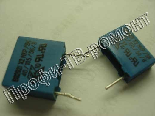
3113.) PHILIPS RT136V. Fault: after switching on, it works for about 20 minutes, and then the raster collapses into a vertical line 3-4 mm wide. Since this line has some kind of width, it is clear that this is not a break, but most likely the well-known blue capacitor from PHILIPS. Replacing the suspicious capacitor with K73-17 - 0.68uF 400V solved the problem.
3120.) Philips 21PT1354 \\ 58 chassis L9.2 Fault: exits standby mode for a second, and turns off again. Faulty (loss of capacitance) blue capacitor 2420 (560nF 250V), which is heated by a nearby two-watt resistor (did not remember the position).
3125.) PHILIPS 28MK2490. Fault - the image floats vertically and to the left horizontally. With warming, a breakdown in general synchronization. The reason is the synchro-processor 7701 TDA2579B.
3129.) PHILIPS 29PT9008 / 12 chassis EM2 Malfunction: when turned on, it appears high for a second, then the TV goes into standby mode, the LED on the panel flashes. The zener diode 6405 (protection) was unsoldered, the TV turned on, the image turned on, the voltage on the + capacitor 2642 100.0x50 gradually increased from 0 to 70V. + a capacitor connected to the cathode of the zener diode, having passed through the chain along the base of the chip of the transistor 3465, it found a dangling SMD resistor 5464 (22 Ohm). So it all began. The troubles did not end there! Not adjustable pillow. I asked again 24C32 - to no avail! Near the optocoupler (through which the correction) I found another dangling SMD resistor (100 Ohms), it seems to be a whole, but in the middle of the zero there is a small hole, I saw through a 10X magnifier. I reshooted the saved firmware and everything fell into place!
3134.) PHILIPS CTV-8148 Fault: there is no line and frame synchronization, and when you try to configure new programs - he does not see them, that is, skips, does not stop. The resistor R235 turned out to be open, according to a circuit with a nominal value of 270kom on the 33 foot of the TA8659AN video processor.
3141.) PHILIPS 28PW5324 / 01. Fault: when turned on, the PSU beeps. BP is working. In the horizontal scanning module, the 6N60. \u200b\u200bFailed, not a short circuit but 35 ohms. After the replacement, the TV turned on, but does not completely expand the line, 6N60 is heated. The horizontal scanning module was removed from the mono board, in the module there was a swollen capacitor 390 n near the output. After replacing the capacitor 390 n, everything is OK.
3142.) PHILIPS 2844. Fault: with heating it “turns green” and switches off spontaneously. Framed TDA6107 - the result is the same.
With a light tapping on the neck of the tube, color flare. We turn off the standard glow (after measuring the U glow),
we wind 2 turns of a well-insulated wire onto the stitcher core and connect it through the standard resistor to the terminals of the kinescope glow. Turn on everything OK. U glow before reworking 6.2V after 6.3V.
3151.) PHILIPS 14PV162 / 58 Fault: does not exit standby mode. BP is working. After a standard CP check,
entered the personnel TDA3653C (short in nutrition). The most interesting thing is that the chip dangled between the radiator and the clamp
the bar. After the replacement, nothing has changed. On the same board, I found two charred resistors connected in series to the anode of the Zener diode TL431C. Phoned TL - partially broken. Replaced and it all worked
3152.) PHILIPS 14PT1345 / 58, chassis L9.2E AA (Polish assembly). Fault: after 20-30 seconds. after the start, he goes into the duty room, only “snow” is displayed on the screen. Detailed testing showed: dried electrolytes of BP in the primary and secondary circuits. And as a result, overstatement of supply voltage. As well as the poor quality of rations in BP, SR, KR, etc. It also turned out that the 24C08 memory chip failed. After eliminating the above defects, the TV works fine.
3154.) Philips 25PT4503 / 58 chassis MD1.2E / AA Malfunction: the line transistor BU1506DX breaks through and can not immediately after a few hours of operation, after the workshop came to me, the service said that it was necessary to change the line transformer. The line transistor in the service was replaced by BU508DF, I decided to install it according to the BU1506DX scheme, but I did not find this transistor on the Mitinsky radio market, I had to take the BU1508DX and everything was checked as to the horizontal scan. The TV, after replacing the transistor, worked, it worked for 8 hours. The next day, the TV did not turn on, the BU1508 made its way right away, once again everything was checked, the only thing that turned out to be that the BU508 and BU1508 were fake, then I replaced the TV with BU2508DF for more than a month, but still the transistor burned out. After replacing the next transistor, when the TV was turned on, a spark jumped in the area of \u200b\u200bthe deflector; after its dismantling, ring cracks were detected on the connector. On the deflectors there is a printed circuit board to which the connector is soldered, around the legs and cracks formed. It was possible to solder without removing the deflector, but just in case, the entire connector disappeared, all the more so since it was not necessary to reduce the rays constructively, as if in a monolith with information magnets. The line transistor now costs a BU2506DX.
3156.) Philips 20GR1250, an ancient unit was purchased in Germany. Fault: a problem gradually appeared - the sound is very quiet and distorted. UMZCH is in order, it works properly from an external source. I rummaged through all the secrets of repair, I did not find anything like this for this TV (apparently in Russia there are very few). I tried to watch the secrets of such televisions such as Recor and other Philips models on the TDA8305. He measured voltages, changed capacitors and electrolytes and ceramic (I read in some secrets that they are sometimes faulty; I just did not understand what to break into them). Once again, taking up his repair, I found that when I touched certain contacts, the sound quality improved slightly. As a result, by the method of scientific poking, I found out that it is necessary to adjust the contours of the TDA8305 hanging on the 13th leg (designation on the scheme 5034, 5035). To get the best effect you need to adjust at maximum volume.
3164.) PHILIPS 14GR1221 / 59R, Fault: everything works fine, except that it does not go into the tuning mode for channels, and the sound is not fully added, the TMP47C434N-3415 processor does not rush to change it, the memory was 24C02, you can put it empty No firmware required.
V. Eremin
The TV does not switch from standby to working. When you try to switch, the standby LED flashes, but does not go out.
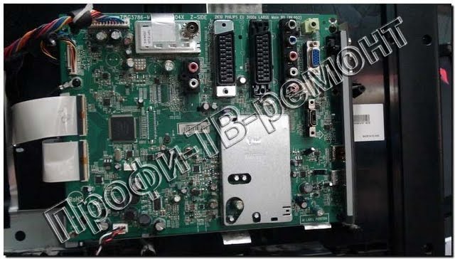
Structurally, the main electrical part of the TV consists of two modules: on the first there are signal processing nodes and a control device, on the other - a pulse power supply, output cascades of horizontal and vertical scanning, and ULF. The modules are interconnected by cables with connectors.
The power source generates voltages for the control device, horizontal scanning, VLF and video amplifiers. Voltage is removed from the additional windings of the horizontal transformer (TDKS) to power the output stage of the vertical scan, video amplifiers and the digital audio processing unit, located on the first module as a separate board. Power is supplied to the horizontal line output stage through a jumper in the loop connector going to the deflecting horizontal coils.
Simplified electrical circuits of the output circuits of a switching power supply and horizontal cascades are shown in Fig. 1 and fig. 2 respectively.
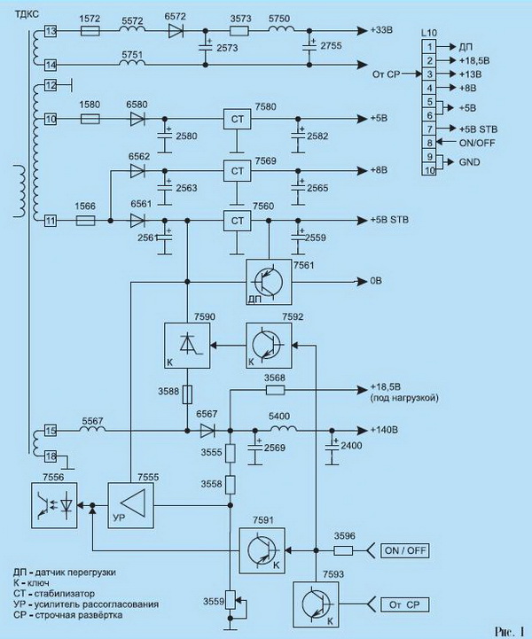
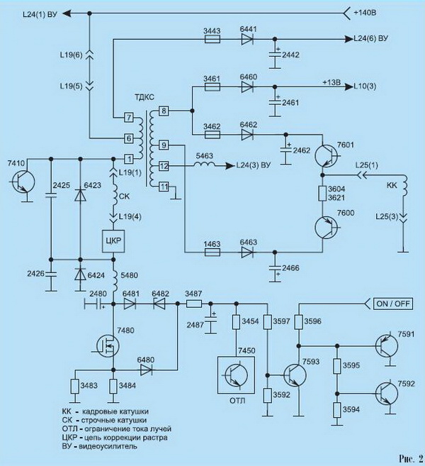
All numbering of elements corresponds to the inscriptions on the printed circuit board.
The troubleshooting technique is as follows.
1. Disconnect the cable from the L19 connector, i.e. turn off the power of the lowercase, and therefore the personnel scan. Trying to put the TV into working mode.
2. If the malfunction persists (the standby indicator lights up, and blinks when you try to switch the TV to operating mode), then first of all check for the presence of the ON signal (+5 V) on contact. 8 L10 sockets, serviceability of keys on transistors 7591, 7592, 7593, overload sensor on transistor 7561. Make sure that there are no open safety circuits, overloads on the +33 V (VLF) and +140 V circuits (video amplifier board through terminal 1 of the L24 connector) as the most likely. Note that the key malfunctions on the thyristor 7590, the mismatch amplifier 7555 and the optocouplers 7556 lead to a general blocking of the start of the switching power supply and are not considered in this case.
3. If the TV has switched to operating mode (the standby indicator has changed the color of the glow from red to green), then check that all voltages correspond to the nominal values \u200b\u200band make sure that the voltage is on contact. 8 of the L11 connector (not shown in the figures) of horizontal triggering pulses coming from the control device.
Further localization of the malfunction does not have features: all power elements of horizontal and vertical scans, safety circuits, kinescope beam current limiter sensor on transistor 7450 are checked. If necessary, rectifier diodes can be sequentially disconnected from the additional windings of the horizontal transformer
We give an example from the practice of finding and eliminating the malfunction in question. When the power was removed from the output stage of the horizontal scanning, the TV immediately switched to the operating mode, which directly indicated a malfunction in the horizontal and vertical scanning circuits. However, direct verification of the elements did not lead to the desired result. In a more detailed analysis, it turned out that with an increase in voltage on the damper diode 6423 (BY228; 1.3 kV; 3 A) more than 50 V, the reverse current through it increased sharply. The speed of electronic protection was enough only to ensure that the transition of the diode is not completely destroyed. After replacing the diode, the performance of the TV was restored.
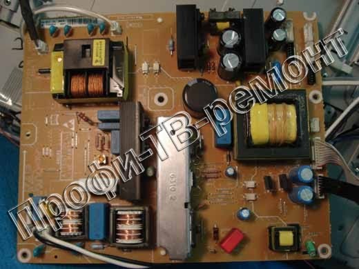
First of all, we examine the power source of the LCD TV PHILIPS. IP is implemented on the basis of a microcircuit (MS) 7520 of type MS44603A, which controls the key transistor 7518 (page IV). In operating mode, the PI operates at a frequency of approximately 40 kHz. When starting the IP in stand-by mode and during overloads, the PWM frequency changes. IP has overload and overvoltage protection.It generates the following output voltages:
16.5 V - power ULF;
140 V - line scan power;
11.3 V - power supply for the video signal processing path, video processor, TV control unit, etc.
Primary chains
The mains voltage through the filters 5500 and 5502 is supplied to the 6502 diode bridge, rectified and charges the capacitor 2508 to a voltage of about 300 V. The demagnetization circuit of the plasma panel is implemented on transistors 7590-7592, varistor 3503 and relay 1580. The relay supplies the supply voltage to the demagnetization circuit upon receipt RESET signal from the control unit. Varistor 3503 provides a smooth decrease in the demagnetization current, since its resistance increases with heating.
When you turn on the TV, the power is on pin. 1 MS 7520 is fed through resistors 3510, 3530, 3529. The output of the microcircuit (pin 3) remains blocked until the voltage at pin. 1 does not reach the level of 14.5 V. After that, the MS generates a pulse, which opens the transistor 7518.
In operating mode, the power supply 7520 is supplied from the winding 8-9 of the transformer 5545 through the diode 6540. In the absence of this voltage, the level on the pin. 1 chip after starting is reduced. When the supply voltage increases to 9 V, the 7520 stops generating triggering pulses, then the start cycle is repeated. You can hear characteristic clicks.
MS 7520 provides stabilization of the output voltage of the IP, for which it implements:
Monitoring the output voltage through the feedback circuit (vyv. 14);
Current control of the key transistor 7518 (pin 7);
Control of the magnetization of the core of the transformer 5545 (vyv. 8).
The stabilization scheme of the output voltage of the IP operates as follows: with an increase in the output voltage of the channel +11.5 V, the current through the photodiode of the optocoupler 7581 increases, which leads to the opening of its phototransistor and an increase in the voltage across the capacitor 2576. The voltage on the pin. 14 MS 7520 increases, which leads to a decrease in the opening time of the key transistor 7518 and a decrease in the voltage of the IP to nominal values.
To control the current passing through the transistor 7518, a resistor 3518 is used. The voltage from this resistor through the divider 3514, 3516 is applied to the pin. 7 MS 7520.
When an overload or short circuit occurs in the load, transistor 7518 closes. In this case, the voltage on the pin. 1 chip 7520 is reduced and the formation of triggering pulses stops. Then the cycle of starting the microcircuit through the resistors 3510, 3530, 3529 is repeated.
While the transistor 7518 is in the closed state, the energy stored in the core of the transformer is transferred to the load. Output voltage 9 transformer 5545 at the same time positive. At the moment when all the energy of the core is transferred to the load, the voltage on the pin. 9 5545 reverses the polarity. This voltage is applied to the pin. 8 7520.
Upon reaching the exit. 1 7520 voltage of 14.5 V, the chip goes into startup mode. At the same time, it provides a smooth increase in output voltages to the level of the operating mode. The transition time to a full duty cycle is determined by the voltage on the capacitor 2530, which is discharged at the time of switching on.
In standby mode, the IP operates at a frequency of about 20 kHz. The frequency is formed by the internal oscillator of the chip 7520 and is determined by an external resistor 3536 connected to the pin. 15 7520. The threshold of the minimum load IP is determined by a resistor 3532 connected to the pin. 12 7520.
In operating mode, the frequency of the internal generator increases to approximately 40 kHz (determined by the capacitor 2531 and the resistor 3537 connected to the pin 10 and 16 of 7520).
Overvoltage protection is triggered when a certain level of voltage on the pin is raised. 1 7520 (usually with a voltage of more than 17 V the MS 7520 goes into protection mode). Further, the IP switches to start-up mode and, if the cause of the overvoltage is not eliminated, then protection mode is switched back on, etc. The “Stand-by” LED on the front of the TV starts flashing.
Audio processing unit for LCD, LCD and LED PHILIPS TV
The node allows you to decode the following sound broadcasting systems:
FM mono (M, BG, I, DK);
NICAM (digital stereo sound standard, used in Eastern Europe, England and France): FM-stereo, NICAM LL ", NICAM I, NICAM B / G, NICAM DK;
2CS (analog stereo standard, 2 carriers, used in Germany and the Netherlands): FM stereo / mono (all standards 4.5, 5.5, 6.5 MHz).
Base TV models include 2CS and NICAM LL / BG / I decoders on a 7250 chip.
The audio signal processing path (A10, A11 on page II, III) is based on a digital sound processor such as MSP3415 (7833) (page VII). The processor provides volume, bass and treble, balance, surround sound, sound effects and the choice of sound source.
Vase models are not equipped with an MSP3415 sound processor. Instead, the Smart Sound A11 board is installed on the TV (page VIII), which provides tone control for two channels based on signals from the A7 control unit.
Signal processing path FM-mono in LCD, LCD and LED TV PHILIPS
The intermediate frequency signal from the tuner (pin 11) passes to the bandpass filters 5002 and 1003 and is fed to the pin. 48, 49 of the 7250 microcircuit, where the composite video signal is extracted (p. VI). With vyv. 6 of the demodulator, the video signal is supplied to filters 1001 or 1002. The choice of filter depends on the state of the DUAL / MONO signal generated by the control unit A7. Next, the signal returns to pin. 1 7250 chip for demodulating sound. Demodulated audio signal with pin. 15 7250 goes to the audio signal processing unit A 1 and then, after adjusting the timbre, to the low-frequency power amplifier A12 (page IX). On the SCART connector (board A15), the sound output signal is received from the pin. 55 of the 7250 chip. An external sound signal from the A15 board (page IX) is sent to the pin. 2 microcircuits 7250 and further on pin. 15.
NICAM Signal Processing Path
The P2LLp signal is used to switch between Nicam L and L standards. With this signal, the corresponding band-pass filter is selected. The intermediate frequency signal is sent to pin 55, 56 of the video processor
7250 (p. VI). From its output (pin 2), the signal is fed to pin. 58 of the 7833 sound processor (p. VII). External audio signals Ext1 and Ext2 are fed, respectively, to the pin. 52, 53 and 49, 50 of the sound processor, and are removed from the pin. 36, 37. Then, from the output of the sound processor 7833 (vyv. 28, 29), the signal goes to power amplifiers 7950 and 7951 (A12).
2CS Signal Processing Path
The IF signal goes to pin. 48, 49 of the video processor 7250, and with its output. 6, a composite video signal is removed, which then goes to the pin. 58 of the 7833 sound processor, where it is demodulated. External audio signals are sent to the pin. 52, 53 and 49, 50, output signal with pin. 36-37 7250 is supplied to the SCART connectors. From the outputs of the sound processor 7833 (vyv. 28, 29), sound signals are sent to the 7950 power amplifier. The PIOMute signal is used to block the sound.
Channel selector and video detector LCD, LCD and LED TV PHILIPS
The channel selector (indicated as “TUNER” in the circuit diagram) is controlled via a 12C digital bus. From the output of the selector, the IF signal is fed to a notch filter 5002 (page VI), which is tuned to a frequency of 40.4 MHz and serves to suppress interference from adjacent channels. The signal then goes to filter 1003 or 1004, depending on the type. In total, 5 types of filters can be used.
Video demodulation occurs in the 7520-A chip. The reference circuit of the demodulator 5006 is connected to the pin. 3-4 7250-A. On vyv. 54 of the demodulator forms the AGC voltage. AGC level can be controlled in service menu. Capacitor 2201 connected to the pin. 53 MS, determines the AGC time constant.
Elements are not able to perfectly block the flow of light - the black color on the LCD TV screen is actually not completely black.
Among the shortcomings, it is also necessary to note color distortion and loss of contrast, since the viewing angle of the LCD is not so wide. Because of this feature, LCD TVs could not catch on for a long time, but now, thanks to the efforts of the developers, the distortions have become almost invisible.
The advantages of TVs with a liquid crystal screen include a wide selection of models with various indicators of brightness (from 250 to 1500 cd / m2) and contrast (from 500: 1 to 5,000,000: 1). Due to this, the buyer can purchase a device that optimally combines the required image quality and affordable price. In addition, LCD TVs are lightweight and thin, so they can be placed on the wall.
But the greatest merit of liquid crystal technology is in its mass character. Due to large-scale production, prices for LCD TVs are now lower than for other similar devices.
From the output of the 7250-A demodulator (pin 6), a 3.2 V-wide video signal is fed to a filter 5202 1200 1203 7252 7253, which suppresses sound signals and then goes to the video signal switch. Using the switch, one of the video sources that are connected to the pin is selected. 13,17,11,10 of the 7250-V video processor.Luminance and chrominance signals are extracted from the video signal. Filters corresponding to various color coding systems are connected to the pin. 34 and 35 video processor. The allocated and delayed luminance signal is fed to the pin. 28 chips, and color difference r-Y signals and B — Y — on the pin. 30 and 29, respectively. The decoding system for AL, SECAM, or NTSC color signals is selected via the I2C bus.
Vyv. 23, 24-25 7250-C are intended for external RGB signals and service information signals from the control microcontroller. Vyv. 26 - input control probe signal FBL. If the FBL signal level is in the range from 0.9 to 3 V, then the “insertion” of RGB signals into the image occurs using the internal keys of the video processor. From the outputs of the 7250-C (vyv. 19, 20 and 21), RGB signals are fed to the picture tube board (page X).
To fix the black level, use pin. 18 7250-C. The black level voltage for each kinescope gun is automatically set to a level that provides a beam current of 10 μA. To limit the maximum values \u200b\u200bof brightness and contrast and, accordingly, the beam current of the kinescope, a measuring signal is applied to the pin. 22 7250-C. This signal comes from the horizontal scanner A2. Contrast and brightness decrease in proportion to the voltage on the pin. 22 7250-C. The decrease in contrast begins when the voltage at this pin becomes less than 3 V. The limitation of brightness begins when the voltage at pin. 22 is less than 2 V. In normal mode, the voltage on the pin. 22 should be 3.3 V.
Horizontal scan assembly for LCD, LCD and LED PHILIPS TV
The master oscillator and horizontal synchronization devices are part of the 7250-D chip (page V). With vyv. 40 7250-D horizontal pulses are fed to the transistor 7461 and then through an isolation transformer 5461 to the output stage made on the transistor 7460. The load of the output stage is the horizontal coils OS 0221 and the primary winding of the horizontal transformer 5445 (pin 1-3).
In addition, pads-like distortion coils 5470, 5471 are included in the same circuit (none in the basic configuration). The linearity of the current in the arched coils is provided by a 5457 inductor. Anode, accelerating and focusing voltages are removed from the secondary windings of the horizontal transformer to power the picture tube and the voltage, which ensures the operation of the output stages of video amplifiers and frame scan.
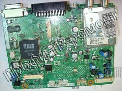
Control node
The control unit is implemented on a 7600 microcontroller type SAA5565 (page VII). Microcontroller provides full control TV, Teletext data storage in the internal random access memory (RAM) and display of service information on the screen (OSD). The TV nodes are controlled mainly via the I2C bus. The amount of RAM in the microcontroller is 2 Kbytes, which allows you to store up to 1000 pages of teletext.
Decoding of 525- and 625-line teletext systems is possible. The volume of the microcontroller ROM is 1280 KB. The supply voltage to the MC 7600 comes from a stabilizer made on a zener diode 6601 and transistor 7603. A transistor 7604 is configured with a RESET signal generation circuit when the TV is turned on.
Control points are indicated depending on the belonging to the functional units of the LCD and LED PHILIPS TV:
A1-A19 - control points for the sound path;
С1-СЗ - control points for the control unit and the front panel;
F1-F5 - control points for frame scanning;
I1-16 - control points of the IF path;
L1-L10 - control points for horizontal scanning;
P1-P7 - control points for the power supply;
51-54 - control points for synchronization circuits;
V1-V16 - control points for the video processor and kinescope board.
The TV may be in the following service modes:
Service mode by default;
Service mode settings;
User service mode.
Let's consider these modes in more detail.
Service Default Mode (SDM)
This mode is used for:
Indication of malfunctions using the LED on the front panel;
Setting control options;
Error buffer control.
Entering service mode by default:
On the RC7150 service control panel, press the DEFAULT button;
On the standard control panel, press the MENU button, and then enter the digital sequence 062596;
Close pin. 20 microprocessor 7600 to the common wire while turning on the TV. After turning on the TV, the jumper can be removed.
![]()
To exit the service mode, by default switch the TV to standby mode. If you just turn off the power, then after turning on the power, the TV will again be in service mode. When you turn off the power or exit the service mode, the TV error buffer is cleared.
When setting the service mode, the default settings are set to the following:
Color System PAL / SECAM;
Receive frequency 475.25 MHz; .
volume - 25%;Brightness, contrast, timbre, etc. - 50%;
The timer settings, the “blue background” of the auto power off, the “Hospital” and “Hotel” modes, child locks, personal settings, skipped and blocked channels are ignored.
In service mode, by default, the following information is displayed on the screen:
LLLL - TV runtime in hexadecimal format;
L90 Air Force X.Y - chassis name and software version number;
SDM (Service Default Mode) - indication of the default service mode;
OP Value (Options Code) OB1 ... OB7 - values \u200b\u200bof option bytes;
ERRs are the five last identified errors. Newer values \u200b\u200bare to the left.
The MENU UP (P +) and MENU DOWN (P-) buttons are used "to select service mode options, and the MENU LEFT (VOL-) and MENU RIGHT (VOL +) buttons to change the option values.
Tuner Menu (TUNER)
IF_PLL - phase-locked loop for PAL / SECAM systems, except for SECAM LL ";
IF_PLL POS - phase lock SECAM LL ";
IF_PLL OFFSET - the default value is 48;
AFW - AFC settings;
AGC - AGC settings;
YD - the default value is 12;
CL - the default value is 4;
AFA - the parameter is read-only;
AFB - the parameter is read-only.
White balance menu (WHITE TONE) LCD and LED PHILIPS TV
The following parameters are adjusted in this menu:
NORMAL RED - red channel gain adjustment;
NORMAL GRE - green channel gain adjustment;
NORMAL BL - blue channel gain adjustment;
DELTA COOL R - black level adjustment in the red channel;
DELTA COOL BL - black level adjustment in the blue channel;
DELTA COOL GRE - black level adjustment in the green channel;
DELTA WARM R - channel white level adjustment
DELTA WARM BL - white level adjustment in the blue channel;
DELTA WARM GRE - adjusts the white level in the green channel.
Possible malfunctions of the LCD and LED PHILIPS TV
Error codes that are recorded by the TV diagnostic system
If the errors are not random, then before starting repair work it is recommended to clear the error buffer (see SDM service mode). You must also carefully study the contents of the entire error buffer, as some errors may simply be the result of other errors, and not a malfunction.
TV malfunction indication via front panel LED
If there is no image on the TV screen, the contents of the error buffer can be read using the indicator on the front panel. When entering SDM mode, the indicator will flash as many times as correspond to the last error number (see table 3). Using the service control panel, you can read the contents of the entire error buffer. To display the second error code, press the DIAGNOSE, 2, OK buttons, the third - DIAGNOSE, 3, OK, etc.
Line scan repair for PHILIPS TV
Check for the presence of a voltage of +140 V on the capacitor 2551 (A1). If there is no voltage, disconnect the 5551 coil. Thus, the horizontal power circuits will be disconnected. If voltage appears - line scan is faulty.
Possible reasons:
Faulty transistor 7460;
Defective elements providing the transistor 7461;
There are no horizontal pulses from vyv. 40 of the video processor 7250 (A4) to the end cascades of horizontal scanning.
If the transistor 7460 is short-circuited, a characteristic clicking sound will be heard from the transmitter. To determine which part of the horizontal scan has failed (output scan stages or distortion correction circuit), disconnect jumper 9465 and set jumper 9461. In this case, distortion correction is disabled. If the raster appears (with parabolic distortion), the correction scheme is faulty. If there is no raster, there is a malfunction in the output stages of horizontal scanning. On televisions with 26- and 29-inch picture tubes (non-standard equipment), correction schemes are missing.
Repairing the PHILIPS TV Power Supply
The troubleshooting should start with checking the voltage +11.5 V on the capacitor 2561. If there is no voltage, check the fuse 1572 and the diode 6560. If these elements are working, proceed to check the primary circuits of the switchgear.
Check the output of the bridge rectifier - the voltage on the capacitor 2508 should be approximately +300 V. If there is no voltage, check the fuse 1500 and the diode bridge 6505. If the fuse is blown, check the key transistor 7518 for a short circuit and resistor 3518 for an open. If there is a voltage of +300 V, they check the starting voltage of the 7520 chip on the pin. 1. It should be approximately +13 V.
If there is no starting voltage, check the 3510 resistor and the Zener diode 6510 for a short circuit. If the voltage on the pin. 1 chip 7520 is - the oscilloscope checks the voltage on the pin. 9 transformer 5545, as well as the health of the resistor 3529 and the diode 6540.
Check the signal at the gate of the key transistor 7518 (control point P2). If there is no signal on the transistor, check the signal at the output of the chip 7520 (pin 3), as well as the health of the resistor 3525 and diode 6514.If repair pHILIPS TV turns out to be expensive or does not work at all, it is better to spit and buy a new TV, taking into account the fact that they are getting cheaper every year. You can watch the most optimal and inexpensive TV models using the direct links on this site.
We have systematized the most common malfunctions of modern Philips TVs, collected by employees of various service centers
Modern TVs of the Dutch brand Philips, which is now produced by the largest Chinese manufacturer TPV Technology, have always been of high quality and functionality. However, even the most reliable product is not immune to problems associated with industrial defects, violation of operating rules, natural disasters, or the natural wear and tear of indoor units and assemblies.
Here is a list of the most common malfunctions of Philips TVs and their external manifestations. After evaluating them, you can decide whether to contact or you can handle it yourself.
Common malfunctions of modern Philips TVs
- There is an image on the screen, but there is no soundtrack for television programs. The cause of the problems should be found in the sound path of the TV, the failed low-frequency amplifier or the processor for processing the audio signal.
- There is no image on the screen, but there is sound. In this case, most likely, any element of the TCON board or the matrix itself is faulty.
- There is no picture, no sound. Most likely, the problems arose due to the fault of the power supply unit of the TV or its main SSB board. Service workers claim that the Philips 42PFL9603 TV model most often sins with this type of malfunction.
- On the screen plasma tv a vertical band formed. In this case, the image itself is somewhat compressed vertically. With a high degree of probability, we can say that the Y-MAIN PDP panel board is out of order.
- The image is transmitted, but with significant interference. You should check the health of the antenna jack of the TV, cable, as well as the built-in or external tuner.
If your TV is no longer under warranty service, then removing it back cover, you may find additional external symptoms of malfunctions that allow you to make the right decision about the future fate of the device.
External symptoms of simple malfunctions of Philips TVs that can be fixed independently:
- Traces of exposure to high temperatures on the TV circuit board, which did not lead to carbonization;
- Ring cracks at the soldering sites, inaccurate soldering of circuit elements. In this case, the contact tracks of the printed circuit board did not peel;
- Minor damage to circuit elements caused by voltage drops that are not accompanied by obvious external manifestations.
External signs of damage requiring serious intervention from a service center:
- Traces of fusion and carbonization of printed conductors and circuit elements;
- Mechanical damage to the circuit board, the TV cabinet and its screen matrix.
Philips TVs known throughout the world and popular in the domestic market since ancient times. In Russia, their active sale began in the early 90s and continues today.
Currently, Philips TVs are mostly manufactured in Kaliningrad, and component parts for assembly are made in China. Unfortunately, its former European quality of Philips home appliance products has been lost due to the transfer of 70% of the production capacity of TP Vision, a Hong Kong company.
In the repair of Philips TVs, for some time they had their own peculiarities due to differences in circuit solutions from Japanese, Korean and Chinese developers. It was also possible to observe differences in the quality of the elemental base used in the production of blocks and modules.
In recent years, this line has gradually been erased, and modern Philips LED TVs of the Kaliningrad assembly are no better than cheap Chinese brands in quality.
Common defects of Philips CRT TVs
Philips TVs with CRTs are rarely available for repair, but the vast practice of repairing them has been accumulated in all service centers over many years of service. In most cases, typical malfunctions are associated with marriage among the individual elements characteristic of a given manufacturer. The breakers of decoupling chokes in the line scan driver and metal-film capacitors in the circuit of the lower-case deflecting coils will be remembered by the masters for a long time to come.
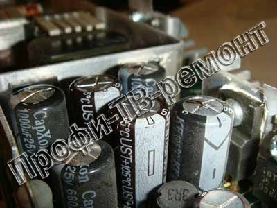
In recent years, CRT televisions with dried electrolytic capacitors in B + sweep power filters often come in for repairs.
Typical defects of Philips LCD and LED TVs
There are a lot of models and chassis of Philips TVs and each type of chassis is characterized by its typical malfunctions, which cannot be described within the framework of one article, so we will point out the most popular defects.
Power Supply
External manifestations:
The TV does not turn on the first time, but after several attempts it still enters the operating mode.
In this case, usually the filter capacitors of the secondary rectifiers of the flyback converter of the switching power supply are faulty. Their replacement is required. The defect is more often observed in Philips TVs with diagonals up to 22 inches, mainly of Polish assembly.
External manifestations:
The TV does not turn on and the control lights do not light, there are no sounds and signs of turning on.
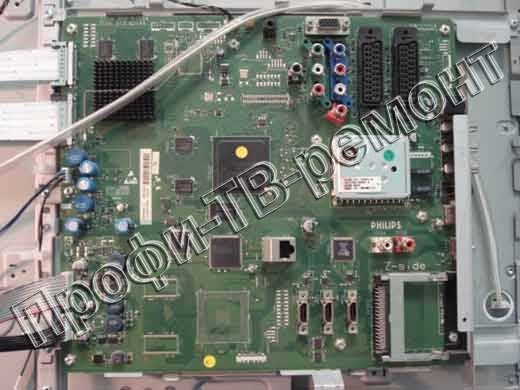
Faulty power supply module or 3.3V standby power converter on the SSB (Main Board) main board.
Immediately note an important point. We strongly do not recommend owners trying to find and replace a fuse. Even if it burned down, the fuse must never be changed without rectifying the fault., which caused his cliff. By itself, for no reason, the fuse in switching power supplies will never blow, it is installed with a 10-fold current margin from the rated one and can blow out only in the event of a serious accident - a short circuit in the input circuits of the power supply circuit.
In addition, we note that the repair of the power supply is always complicated and requires the master to have the appropriate qualifications and knowledge of the circuitry of flyback and linear voltage converters.
In some cases, replacement may be required.
Display backlight
External manifestations:
There is no image, the screen is black, there is sound, but with reflected light, image elements in contrasting areas are weakly visible.
The inverter, the power converter for the lamps or LEDs of the backlight of the LCD panel (matrix), may be faulty.
With the same symptoms, there are often faulty LEDs in LED panels, or contact connections in the connectors or soldered terminals of strips (strings). Dismantling the panel at home is strongly discouraged.
T-con
External manifestations:
Strong color distortion. The image seems to be in a negative and somewhat reminiscent of a signal from an infrared camera (thermal imager).
In this case, two options should be considered. In both cases, the problem is related to the change in the voltage value V-com in the timing controller (T-CON).
1. The panel code is set incorrectly.
The problem is solved by installing the necessary options in the service mode of the TV (Service Mode).
2. Defective buffer amplifier chip in the gamma correction unit.
Need repair gamma corrector (replacement chip AS15F, or AS19F). The defect is observed in certain types of panels manufacturer Samsung.
Self diagnosis
External manifestations:
The red light on the front flashes.
The TV is malfunctioning and is in the self-diagnosis mode of the malfunction. The number of blinks per period indicates to specialists the node in which to look for the problem. A table with fault codes is provided by manufacturers for service centers in special documentation.
St. Petersburg, Bolshevikov Ave., 3, building 1.