The simplest lamp primach (11 photos). Single-tube regenerator, double-tube superheterodyne ... Regenerative primer on 6zh1p lamps
Scheme of a self-contained regenerative primach on a lamp from low-voltage living batteries. The radio receiver has only one radio lamp, supplemented with a minimum number of radio-electronic components. Fallow in the parameters of the coils of the radio receiver can be used in the NE, LW and HF bands.
Rice. 1. Experimental scheme is important for priming on a lamp.
The anode voltage is safe for life and can fluctuate between 20-50V. To ensure the anode voltage, it is possible to vicorate a sprat of successively connected KRONA batteries.
Like a radio lamp (on scheme G-807), you can also use triodes, iron notebooks, pentodies, etc. For example, for this scheme, the praccyvatimut: 6P9, 6P3S, 6P7S, G-807, G-811 and navit GU-50.

Rice. 2. Radio lamp G-807.

Rice. 3. G-807 lamp base.
As a telephone, it is necessary to use high-resistance headphones of the TON-2 type, or connect a TVZ transformer instead, and before that, low-resistance headphones or a dynamic head.

Rice. 4. Radio lamp 6P7S.

Rice. 5. Basement of radio lamps 6P7S.
Coil winding L1 and L2 can be rotated on one single frame. The number of turns is selected depending on the required range, which is accepted. For example, for one of the subranges of KV (40-80m), the L1 spool will cover 3 turns with a 0.5mm dart, and the L2 contour spool - approximately 12 turns with a 0.8-1mm dart, it will work approximately in the 3rd-4th turn of the beast. Coils are mounted on a coiled frame with a diameter of 40-45mm, between coils - 3-4mm.
For those who love the warmth of a lamp candle: you can add a blue light to the lighting of a glass balloon, as a result, you can take even a candle lamp in the same light of the lamp itself.

Rice. 6. The butt of the light of the lamp 6P7S with lightening from the blue light.
Let's have a successful experiment!
After the preparation of the primer of a direct transformation, which, having pleased with its filthy robot, it was repeated one type of radio receivers, and itself regenerative. The peak of popularity of tube regenerative radio receivers fell approximately on the 30-50th anniversary of the last century, which can be judged from the anonymous publications on this topic in the current radio amateur literature. Nadal, the regenerative radio receivers were completely filled with superheterodynes and forgotten for a long ten years ...
On the cob already in the 21st century, they guessed about the regenerators and more and more often they began to repeat them. There have been a lot of publications and schemes for regenerative radio receivers, both on vacuum tubes and on transistors.
For repetition, the design of S. Belenetsky was taken. Tse transistor regenerative radio receiver of a short range:

No annual changes were made to the radio receiver scheme. Added only an electronic power regulator on transistors KP501. Like the end of the ULF with the method of ensuring the guchnomov’s reception, I’m ready to chime in at the Lyon-B radio station.
The final scheme of the radio receiver from the assigned actual modes in robotic transistors is shown below:

Schematic diagram of the terminal ULF on the microcircuit TBA810S (K174UN7):

Regenerative radio receiver operating in the range of 2.9 ... 3.7 MHz and building reception of radio stations, which work both with amplitude modulation (AM), and with single-range (SSB), as well as telegraph (CW).
This regenerative radio receiver may have the following governing bodies:
Attenuator (replacement resistor R18470 Ohm);
Adjustment to the frequency of radio stations (replacement capacitor C7 6 ... 500 pF);
- Riven regeneration (replacement resistor R1 10k);
LF strength (change resistor R17 22k);
The necessary coefficient of strength of the forward ULF on transistors VT3 and VT4 is installed by the substroyuval resistor R12.
The main knots of the regenerative primer are:
regenerative cascade on transistors VT1;
Detector on transistors VT2;
Front ULF on transistors VT3 and VT4;
Electronic volume control on VT5 transistors.
Like a capacitor with a changeable capacitance of KPI in the radio receiver "Ural-auto" with a range of change in capacitance of 6 ... 500 pF, which can be verniered from up to 1: 4. This vernier does not provide a comfortable setting at the radio station, due to the small increase, so the range of robotic reception of 2.9 ... 3.7 MHz was divided into two sub-bands - 3.6 ... 3.7 MHz and 2.9 ... 3.4 MHz. In the range of 2.9 ... 3.4 MHz, they use the so-called "radio hooligans" from the amplitude modulation. Tsіkavo will try this regenerator in a different range.
The choice of tensile capacitors C17 and C18 was carried out with the aid of the KONTUR3C program.
The results of the analysis are presented in the table:
C17, pF C18, pF
2.9…3.4 MHz 560390
3.6…3.7 MHz 270750
Coil of inductance L1 is wound on Amidon T 50-2 rings:

Number of vitkiv-35, wired PEL-0.5. Inductance 7.1 µH.
Regenerative acceptance of selections on a different board, and on the same experimental chassis as
The glaring look of the chosen priymach on the chassis:

View of the beast with deakim inscriptions:

Raztashuvannya of the main elements:

The folding of the regenerative primer did not create any particular difficulties. Usі modes of transistors were installed automatically similarly to the author's description. Pidhіd to the generation mode є dosit smoothly. It is good to see when the oscilloscope controls the signal of the local oscillator on the emitter of the transistor VT1 - in the world, the increase in the resistor R1 of the voltage on the base of VT1 smoothly, without stripping, the amplitude of the high-frequency voltage increases from zero to the maximum value.
The first switch-on zbentezhilo-in the dynamics of silence, the tension was not on the ethereal noise. Bula vikoristan antenna Inverted V band 80m. As it turned out, the connection of the antenna visualized the generation of the local oscillator. Changing the number of turns of the coil from three to one eliminated the problem. Now it’s time for the connection of the antenna to listen well to the ethereal noise at the exit of the receiver.
I had a chance to tinker with the laying of the range of operating frequencies. As it was shown more, the choice of tensile capacitors was used for the help of the KONTUR3C program. For a correct selection of capacitances to be drawn, it is necessary to correctly set the value of the local oscillator input capacitance + mounting capacitance. In my mind, the value was getting close to 68 pF.
This regenerative primer was tested for an hour of work on the air on the 3.5 MHz band on the 1st day of 2017. Having shown a good robot, the local oscillator can be stable enough.
Otzhe, I turn to those regenerative lamp primach. . And now the hour has come, go to the very radio. I’m guessing that I’ll take after the image and likeness of the miraculous region, which I uttered Romas-LY3CU. I am in my experiments in solidarity with him, I don’t know better than a lamp 6G7 for this primach. Vaughn gives even more strength, especially in the variant with an antenamic subsidy, also on the 6G7 triode. At the same time, the sound is even purer and more receptive. Other lamps (because of these schemes, which I knew and for my own authority) I could not bring me to such a vibrancy of sounding.
Otzhe, scheme.
After that, as a sound frequency booster and sound properly, the time has come to go to the radio. The regenerative receiver is just as simple as a radio. Yogo vikoristannya classically transmits listening to local radio stations, but our receiver is wonderfully suitable for short whistles! The first receivers through the hours at the radioamators of the first half of the 20th century had a sufficient number of details, that and often the very ability to reach the professionally prepared radio in the store worked on one or two lamps. The butt of such a primer is Morgan's regenerative primer, which, as I see it, formed the basis of our unit. I already torkavsya yogo trohi, but still I promised to turn to the new one.
| Morgan's Regenerative Primer |
Try to grow up with yoga attachment. I’ll also guess that I’m not motivated to work without interruption this priymach without ULF.
antenna
Zliva mi bachimo antenna, connected to the circuit through parallel sub-construction capacitors. It’s a pity I don’t know so much about antennas yet, as I would like to, so I’m not going to say anything about them, except for what I’ve learned. I will only say that for such receivers the antenna is not the most important detail. There are no antennas - there is nothing good to slander for everything. Good novelty is that for the antenna, the zіyde shmatok drota zavdovka wants a few meters. And so, the antenna is bad, but in the case of radio technical grounding it won’t give a lot of bad results, it’s possible to allow you to catch some amateur SSB stations. Antenna bazhano, zvichayno, mother zovnіshnyu, tobto vyvedenu for mezhі booth, especially like booths, like mine - a concrete box. Tue, I unplugged the antenna at the apartment and installed wires on the balconies vzdovzh vіkon - it’s already bad to go out. Then, having stuck my old wood, I now throw out a її zі darts at the window perpendicularly to the booth. It’s not obov’yazkovy zahіd, but I’ll get better in such a way, and so, I don’t give a damn, what judges will think about me. Admittedly, I (to see them) do not smoke at the window, but simply not empty, I don’t chip anyone, I hang the antenna.
I was thinking about radio engineering grounding. Vono also needs obov'yazkovo. Yak yoga robiti - individual nutrition for the skin. At a private booth, you can simply bury a booth in the ground with a large flood near the orphan booth. At the rich apartment booth, which is better for everything, the contact with the earth can be scorched by the trumpets that go to the basement. However, on my pipes there are 100 and 100 volts of magic, for some of them (as if other electrical equipment was hitting at the same time) it’s quite striking to hit with a strum :) , Connecting grounding through a small ceramic capacitor at 180 picofarads (small, natural, approx.). So, first of all, I have secured my receiver in the form of untransferred voltage on the battery. In a different way, in the case of some kind of forgiveness, the installation turns off the ingress of an unsafe voltage on the battery. I’ll tell you that in a bagatokvartirny booth, access to the batteries of the central scorching can be impersonal people at once, because of their safety, at any other time it’s not possible to bring a high voltage to the batteries! It's a pity that some people don't have batteries connected to them, and for that I would have a hundred volts, if I wipe on the radiator and drank and stumble violently against the computer case.
So, as a grounding, vicoristing and gas supply pipes are blocked, so that electricity and gas - tse, you yourself, are not safe sum. Zrozumіlo, for radiotechnical grounding, it was fenced and grounded in rosettes - it has another recognition. You can try the radio technical grounding through the metal balcony railings. Possibly, metal z'ednany with fittings a booth and go under the ground. However, in my opinion, the railing did not give positive results. In fact, my first grounding was a great dart dart like a bi on an antenna counter, just connecting to minus priymach and wallowing on the bottom - giving weak results, but better, lower without it.
The practicality of the antenna, which I have seen, I check with high-resistance headphones. It’s not a big deal, it’s a good way, but I connect the antenna to one contact of the headphone, and grounding to another. Headphones are not switched on between the antenna and the "ground". Although the contact is good, they have a slightly weak noise. Well, obviously, the best headphones and speakers will not give such results. Headphones are needed more lower than 1000 ohm. I spared my time to buy this at a flea market.
Kolivalny circuit
Antenna, as it was assigned higher, is connected through a built-in capacitor. Here vikoristano at 4-80 picofarads. Pіdіyde zvichayny pіdryadnik. This capacitor is needed to regulate the vibrancy of the receiver, which was given a series of inclusions in the ground circuit. Most of all I was honored with a vikonan cat with a millimeter-sized middle dart on a frame in a can of sour cream in 4 turns every millimeter :) You can take it without a frame, but wind it up foldably. You can take a great bag of accommodation. Parallel to the coil, there is a built-in capacitor for 10-365 picofarads (one section of the capacitor is similar to the old lamp receiver). Changing the capacitance of the capacitor changes the frequency of adjusting the receiver.
Gridlik
And more shortly: gridleak. So I realized that the coil of the grid :) The cooler in the regen is called the resistor-capacitor pair between the kolivatny circuit and the grid of the lamp-regenerator. Especially those that can only have a resistor with an even greater support (meg and more), and a capacitor - with a small capacity - tens of picofarads. You can experiment and get your own grill.
Regenerator lamp
The 6BF6 triode is victorious in the scheme, so I don’t have to talk about it in particular, because I don’t know anything about imported lamps, there are a few pieces in the collection from many countries REV, but that’s all :)
Our 6G7 miraculously fits the role of this lamp - a triode-pending diode near a metal canister with a wine screen. The lamp regenerator sounded planted by the cathode on the "ground". If we put it in the cathode, then we will lock the lamp, so that the grid will immediately appear positive for the cathode, and the potential may be closer to zero. However, even though the cathode is still necessary, the entire cascade of the lamp (gridlik, cathode, capacitors in the anode, etc.) should be grounded through the whole cath resistor. So we will not fence the city. A 500-kilometer potentiometer is connected to the anode of the lamp with a middle point. Tse zvorotny zv'yazok. But the option with the єmnіsnym regulator is significantly shorter!
Zvorotniy zv'azok
Most of these devices for adjusting the depth of the turn signal are replaced by changing resistors. Romas-LY3CU in his favor promotes a miracle solution - replacing the potentiometer with a replacement capacitor. This is truly a miracle option! Regulation immediately becomes significantly smoother. The regulator of the whistle blows here from the coil of the whistle blow, the regenerator works for it itself.
Cot zvorotnogo zv'yazku.
To pay attention to the detail, marked on the diagram "Tickler coil" - this coil is inductively connected to the coil of the kolivatny circuit, and therefore it is to blame but placed on the same frame with it, but on a small section. For whom I'm glued in paper's fluffy kіltse, like it's possible to rush at once with this cat back and forth along the frame for fixing the glybin of the zvorotny zvezku. It’s not handy and not safe to work for an hour of work and take it (on the anode voltage coil), so we need a regulator of the return link at the sight of a resistor or a capacitor. However, in my case, I have stopped the rotary mechanism, as a result of which my coil is turning according to the surface of the coil of the ringing circuit, by the same time the sound is either weaker or stronger, expanding the range of available frequencies for the regenerator on one coil, helping to roughen up regenerator.
Age regenerator for those i regenerator, scho win mayzhe generator :) . Our task is to get up to the point where you pick up the ringing sound, so that the lamp leans on the damage, so that it whistles and falls into the self-excitation mode. And if we continue to stretch this generation threshold so that we bring the lamp up to the new one and deprive it of it in the same state, then the lamp starts to become even a good booster, with which we detect our signal, seeing the new sound frequency! And everything depends on the correct rotting of the coil of the serum and the selection of the regulator of the depth of regeneration.
A coil in three turns with a medium dart with a thickness of 0.3 mm, approximately of the same diameter, is suitable for a coil with a link for my chotirivitkovo coil. These are not absolute criteria. Try different different cats! The diameter of the frame of both coils is only as short as possible - so you can get the maximum amplitude of the chimney circuit if you need to feed them into the back.
Important: not everything is the same as turning on the cats!
I just painted, how to connect them, explain in words too smoothly. It's easy to get confused. Kіlka once perevіriv again, nibi everything is correct. Zagalom, the idea of \u200b\u200bchomu, that the coils are co-directed, so that an inductive link was formed between them. As a catcher, the possibility is great, that the connection of the cat is entangled. At the norm, when they are attached, the sound of the ether may appear. There is no need to change the lance of the kolivalny circuit and the cascade of the lamp 6G7, so there is no urvishch, a direct anode strum 6G7 flows through the coil, which is more confused than the connection of the coil. It is possible, it is also necessary to change the capacitor linking with the ULF. The ULF itself does not need to be dug, to which mi yogo was already prompted and nailed, but at the same time a large part of the scheme :) Why is it so important to take care of the sequence of folding.
The noise of the air appears without the connection of the antenna and the grounding, wanting to slander the receiver without them, perhaps, nothing can be done.
Head phones And the best pidsiluvach!
I’ve already written that there’s not much to hurry up and hear with squeaks and claps at high-resistance headphones. Take your own pidsiluvach. It is connected through a good capacitor with a capacity of 2200 picofarads. 2.5 megohm switching resistor, as you know, so as not to burn the cats in the headphones with a constant strum.
A variant of the scheme, as I chose:
Let's go through the details:
R20 - anode strumoobzhuvalny resistor. Yogo opir - from a few dozen to a few hundreds of kilos. It’s worse, the less strum goes through the lamp and the weaker sound between the coils L1 and L2. But the trick of the regen is such that the lamp goes well to the threshold of generation, if the voltage is low on it - so 55 volts! This circuit will have close to 75 volts on it. In such a regime, it’s out of the question, as it happened to me, (unfortunately, it’s less subjective) more powerful, and more stations are received. Zagalom, I vyrishiv zupinitsya on 220 kіlom in the anode, at Romas 120 - IMHO: obmal. You can reduce the voltage, shunt the lamp with a resistor, to bring it to low values. Generation is welcome, but sensibility falls. The coils are already turning the stars into place, quickly stop putting the lamp into generation. Bet 200 kilos with a zagal.
C14, C15 - decoupling capacitors of the anode lance. We don’t need a high-frequency signal, which still penetrated into other lamp cascades, so capacitors should be installed in the region of hundreds of picofarads for high-frequency separation, but C14 is also low-frequency filtering, moreover, along the entire anode lance, how can you please.
Dr1 - The detail is very important! So, you can go without a throttle. Pratsyuvatime, ale zovsіm not like that, like a drosel. Let's talk about yoga recognition. Vіn inclusions in the anodic lance, it is to blame for missing the post-strum (which is so small here, so that the community of the drotu, it would have been used, is uncritical - nothing can be burned out, but there is a nuance!) the language and the capacitor are connected to the ULF. Now show that yoga is dumb. A radio frequency is induced on the coil of the link, which is generated by the lamp, and also sound detection, visions for sound sound pass through it. more accurate detection by a lamp. There is no throttle. It would be better, that th scho? For the sound, the choice is obvious - to go through the capacitor, the connection was given at the sound cascade. It is hard to pass through the anode 220 kilom. So, so it seems without a throttle. But what if you want to put a choke with a good inductance - close to 10 mH? Rozrahuyemo reactive support of such a choke for radio frequency. XL = 2πfL. Let our frequency be 3 million hertz - the lower boundary of short waves. For her, a throttle to create an opir of 188.4 kilos! Tsej opіr, scho vinik on droselі, to increase the tension of the strengthening of the radio in the receiver. Throttle here є pіdsilyuvachem radio frequency! At the same hour, for voice frequencies, it doesn’t matter that at 100 hertz the throttle will give an opir of only 6.28 ohms and it’s easy to skip it to the capacitor ... but ... the axis here is a nuance. We don’t in any way vouch for the wires at the receiver, vvazhayuchi їх equal to zero, but what if the wire is long and thin? If you wind the throttle with a thin dart, then it will grow, possibly up to hundreds. Tse is already critical for any strums. Shards of stench are weaker, not stronger, then the throttle from a thin dart is more likely to muffle the sound of detection by a lamp. It’s not so much already, but it’s obvious. And to that, I’ll take the postings for that comrade’s drosel with a nonchalant raja! Zagalom, go out, zvichano, no longer economically, but we are not in mass production, but for ourselves! :) You can pamper yourself with expensive throttles :) Before we talk, as I wind the throttle. Garazd, but you can increase the inductance by inserting a core into the choke! It is fair to respect, but radio frequencies do not like ferite cores. I read that they stink a lot of energy and fade away, I also suspect that ferit such a strength, like a broken throttle, will not give. I put the throttle with a primer with a ferrite and subjectively my repetitions sound better, although it is possible for us to do that, however, it is important for us to get the maximum from the radio, especially since the antenna is weak. So sho motaєmo, motaєmo drosel, panov!
С13 - obov'yazkovo pіdstroyuvalny. If it is already stressed with them, then you can put a replacement for a new potentiometer, like in Morgan's receiver, by shunting the coil. Ale raja, put the capacitor itself, moreover, repeat it. If it is greater than 365 picofarads, then you can do it, but you can make the generation more foldable. You can try to connect with him successively, the law will make the total capacity smaller: C1xC2 / (C1 + C2). . I honestly know that I turned to the first option. Self-conscious wheezing and zamikaє, zrobiti as if it were not necessary, I also got enough of it. Sound up, know a good newties of the snake, not more than 100 pikofarad, INAKSHE SMUGA regaluvANENSUS SAME, but without a cat of a gigal Zv'yazku, I am in the back of the General Points of the General, the Putzi Puteli. radio frequencies. Zagalom, set the cob for the cob, picofarad at 300 :)
So, how does it work. Conder locks our cat zv'yazku to the "ground". As a result, I create a reactive reference for the frequency that is being detected. It's a pity, not to go so far, that the capacitor, at a fixed position, turned on the generation. Therefore, due to the different frequencies of the wines, there can be a difference in throughput. For that very reason, I smashed the coil of the zvorotnoy zv'yazka with a fluffy one, so that it would be possible to lash the zv'yazok with it rudely, and then we'd already softly ring it with a conder.
I don’t know what a competent explanation of the process is, what it is, but I will understand it in such a way that it is possible to build a KPI, how to make a call, how to change the amount of transmission of a detected signal. With a minimum capacity (the plates are hanging), the tie is even weaker - it's a catch. Far away, thrusting the plates, generation is being generated, an AM signal is being heard, you can hear the HF radio stations. Continuing to put the plates in, we create enough capacity, so that the low frequencies start to fall to the ground, the sound becomes characteristically high, one-smog modulation or SSB goes on. I understand the process in such a way that the KPI nib less often detects the signal stronger and stronger, letting out lower frequencies, if we have enough plates. But it’s hard to figure out the SSB-station, because we need to turn the receiver so precisely, so that we have a swarthy, for example, they filtered the SSB-station clearly in such a manner, otherwise the sound is either unnaturally high, or unnaturally low, or it’s impossible to pick it up. In a similar way, the coil of the zv'yazku is used, but it is also necessary to remove the coils for the effect of a similar hanging of the plates.
Coils L1 and L2. Well, enough has already been said about them. You can practically be the same, but there are nuances. Practice has shown (here again a few audiophiles) that great cats from a tovstoy dart show better results. I suspect that this conductor may have a smaller opir, which can be critical for the weak, not yet strong, strums. Possibly, on HF, a superficial effect begins to appear, HF streams begin to appear on the surface of the conductor, which is more, more quickly, again, through the falling support. Zagalom, I recommend a millimeter wire for the coil to the contour and here 0.3-0.5 mm per coil. The lower coils require less work, the lower ones have the main coil. Try picking up the right way. I pіshov a way of zminnikh cats. Having made a difference for them, so that you can change them. The main cat I have is screwed to the terminals of the socket, for the connection, having broken its roses.
C17, R21 - griddle. I'm working on a wiring harness, which is more likely to work with a resistor, shorted to "ground", if you can do it in parallel with a capacitor. The resistor is to blame but not less than a megohm, you can try 2, 3 megohm, for some lamps you need 10 megaohm. Meni here was honored with 1 megohm from the grid. The less opir, the more strength, but the sacrifice should be brought to the expansion of the smog of the passage. Similarly with a condenser - more capacity - more for smuga, but a little more weak stations. I have a bad antenna, so it's critical for me.
C16 - the culmination of the problem with a lot of missing. In fact, the continuation of the grid, so that this conduit also secures the winding of the grid, the more wines, the more wines let out near the ground, to allow the sound of smuga and not to let the ship stations. Here, I still need to strike a balance. I zoomed in at 56 picofarads. You can put і 120, or navpak - let's say, 20-30. Another option is to increase the capacitor in front of C17, you can also try it.
C18 - one section of the superimposed KPI from the primer. The greater the capacity, the shorter, if you want to make it easier to adjust the station. Ale is classical - tse 10 ... 365 picofarad. Under such an insurance cat.
C19 - call to the antenna. Tse be a substroyuvalny capacitor on one unit - tens of picofarads, there are so many of them in primers. Єmnіst I painted mentally. You can replace yoga with a constant one, for example, put a picofarad of 100, and even better, you can ease the work of the station. Here, again, it is the nourishment of vibrancy.
Criticism of the regenerator
I tried to improve my knowledge of this priymach of the flooring, as far as I was allowed by the day of any technical knowledge :) I suspect that my work can be corrected. Prote, I should like this priymach. Vіn clumsy in the implementation of the duzhe tsіkaviy. There is no other article left, because I did not describe the connection of the antenna substation, but it is also necessary, especially with a weak antenna. Tim is not smaller, regen can have a sea of his own shortcomings
You can get out of the situation by using a path to pick up the scale manually for your change coils with the frequency generator or for the already calibrated scale of another primach, which is called "by ear". I still made my way around the circuit with a generator. . I have created key signs for myself, so that I can roughly know the frequency of listening. Prote, the generator is being re-ordered for less, and it will take care of the scale for the time being. Hocha її vіdsutnіst - sutєviy nedolіk.
Let's continue to talk about the life of the regenerative primach. I plan to discuss my UHF status and discuss the power supply of the indicator. Ale, that's all. Good luck everyone!
E. Aisberg "Radio - tse simple" (E. Aisberg, La radio? .. Mais c "est tres simple!).VC. Labutin, Book of the Radiomaster, Derzhenergovidav, Moscow-Leningrad, 1961
Lumpy.
True, the radio receiver does not take revenge on the low frequency of this noise. All the calls are being transmitted. Also, it’s possible to get a little bit and about the life-time - the anode voltage and the voltage. To improve the high characteristics of the radio receiver, it is better to stabilize the voltage. Tsezovsіm is not difficult. Transformers with a secondary winding, which move, at a time, are rare, winding a cat is not enough to love, you can charge it with an offensive rank. Two transformers of the same type with the same secondary windings are not very difficult to change. At the output of another transformer, we take 220V ourselves, with a galvanic switch in the wire.

Zastosuvshi transformers with different secondary windings, you can take the output voltage.
Like ULF, you can block the active acoustic system from the computer.
In the author's variant, a self-contained lamp podsiluvach was zastosovanny. Vіd new, the voltage of the anode was taken. The radio receiver was connected to the receiver with two roses - a signal standard pin with a diameter of 3.5 mm. and high voltage with roasted, rose DB-9, on the dzherel (pіdsilyuvachi) "mother", so there was less chance of getting in with your fingers.

Otzhe, what is needed.
Nasampered, radio elements. From not the widest, you still need a variable capacity capacitor with a redeemed dielectric, for the radio receiver's chimney circuit. Zastosovuvat widened miniature capacitors with a solid dielectric with imported radio receivers and radio tape recorders not a trace - the stability of the frequency will be low and the adjustment of our radio "floating". Shukati in the old tube radios, fortunately, there are more of them in the hills and garages.
It is unlikely that a capacitor with a changeable capacity will appear under the hand, just like in the diagram. Get out of the position, you can override the kolyvalny circuit. Zruly Robita for the pre -post of special programs, the ledge of Coil 32. Krim Inshogo, Tsist the Singing Street Svobody with the Viyaztovosti - PID handle is good for the Kotushka VID Zv'yazkovoi, the VIDMINITY OF PROTEMITITIONAL, ONE POSITIONAL, ONEDSUMI radio on the other band. The program also allows you to open the coil for the required inductance.
When rozrahunku, slid pragnut to the great value of the diameter of the dart, and the coil winding, to allow the circuit to reach a greater quality factor. Before speech, in view of the design of the coil (cob of the quality factor of the circuit) in the regenerators, it is too rich to lie. The price is paid for the simplicity of the overall design.
Tools.
The radio receiver itself literally struggled “on the knee”, a minimum of tools - the most important set of slusarnyh tools, important for dribbling work, metal knives. Having opened it for drilling, you need a jigsaw for wood and a jewelry jigsaw with files. The frame of the element was sealed with hot glue.
Soldering iron close to 40W from accessories, a set of tools for installation.
Materials.
Crimean radio elements, vikoristan fiberboard shmachok for the top panel of the frame, small shmatochok galvanized steel for the windings, brackets and additional elements, a larger shmaochok for the front panel. Pieces of wooden slats and slats, trochs of reinforcement. It is more attached to the body of the contour coil, the difference between ceramics and polystyrene, then there is an empty “syringe” of silicone sealant. Winding drіt at lacquered insulation for the cat.
Krim overexploited, you still need an antenna that is grounded.
In the author's vikonann, L-shaped antenna was vikonan bula from a winding cord - about 10 strands ~ 0.25mm. It was stretched between several insulators and porcelain “coils” (for some hours, bulbs and electricity were installed on all edges, electrical wiring was installed), on the mountain, under a forged slate dahu, the reduction was wound up from the blocks of booths. Insulators (here, two per skin beam), you can block and more - the more, the weaker signal can receive the antenna. The height of the height of the horizontal part of the troch is more than 7m, and the height of the bottom is 9m.
On dry hills, porcelain rollers or pots can be replaced with a nylon cord. If you want in another way, roztashuvannya antenna under cover, let it be and not metal - not the best option.
The grounding was crushed from a meter-long slushy smog, cast from one point and hammered into the ground to beat a booth. On the other end, an M6 bolt was welded. Between two larger washers, there are tinned copper braids. The rest, wound up to the booth.

The design of the radio receiver can be seen in the photo. The top panel is chipped from fiberboard, front and back, two pine lath legs are installed, fastened with small carnations and glue. From galvanized steel virizana that is fixed behind additional coils and self-tapping screws, the front panel.
Large elements are installed on the top panel. The variable capacity condenser is known with its own special pulley (with a groove for the winder and springs for tension), the winder was taken from a new well. The condenser was installed on a small wooden stand - otherwise the pulleys could not be removed, but it was possible to cut through the gap with a jigsaw at the base.
For manual lashing, stapling verniers from non-abyakim uplifts. The shaft of the crushing shaft is made of a round wooden stick, bearings are made of thin plastic in the form of a plate. Unfortunately, the design of the vernier did not appear far away, the shaft had to be wrapped around small, but still zusills - rubbing the wooden shaft pressed with a stretched cable to the wooden gasket in the middle of the front panel appeared large. Possibly, varto bulo rose the spindles, parts that rub, rub the candles with stearin, or, better, replace the shaft with metal, polishing yoga in the dotik. And the bushing is made of PTFE. Prote, I repeat - the design of the bula is "nakolіnna".
The coil is wound on the body of an empty syringe with silicone sealant. The tube is cut to the required length, the plug-piston is screwed with a long screw. Її, having turned the insertion to the beast, at the same time from the edge - to milk a thin plastic tube while filling the troch with more thickness and looking more aesthetically pleasing.

The plastic spout of the sealant, which is added to the tube, is driven to the cracking and victorious like an improvised nut. In addition, the body of the coil is glued to the top panel with hot glue.
Inspection of parts of the coils of the coil, while winding the windings, finish off with a dart, work better with soldering, scuffing a small lot of lacquer on the dart with gostream wood. The number of turns "before" the introduction is selected experimentally. Tse maє buti mіsce, with some pidkhіd to the generation of the most fluent (begin from the pіvvіtka at the bottom). Generation ("whistling") is due to start approximately 90% of the potentiometer motor to the top one behind the 150K resistor circuit. As soon as it starts earlier, it is even sharper, and as a result, you don’t know how to win the maximum sensitivity and vibrance.
A closer analogue of the "industrial-winter" 6136 - 6ZH4P-DR, but simple, without indexes, it works like a charm. Zastosuvannya screen for the lamp - the sleeve is bent from brass foil, closed with the "body" of the circuit, thereby reducing the guidance.
Good afternoon.
Note
For example, there are two videos, which are approximately duplicated in place of the article and demonstrate the work of the attachment.
I want to let it go, they bastookh tuteshnіkhnіkhni -bastard the electronus, put on on the elektron lamps (specially vene warmth, take the monumental lamp of the structures), ale with the tsomas, he will have a warmth of the frozen with your frequent hands with frequent with your frequent hands. or problems from the search for specific transformers. I want to try the first article to help the suffering, tobto. describe lampov design with a low anode voltage, even a simple circuit, widened elements and daily consumption from the output transformer. At the same price, not a chergovy pіdsiluvach for headphones, but like an overdrive for a guitar, but a richly cіkavіshiy attachment.
What is the design? - Ask you. And my advice is simple: " Overregenerator!".
Supergenerators - all kinds of different types of radio receivers, which are inspired by the simplicity of circuits and incorruptible characteristics, equal to simple superheterodynes. Subjects were very popular in the middle of the last century (especially in portable electronics) and recognized stench in the first place for receiving stations with amplitude modulation in the UHF range, or they can also receive stations with frequency modulation (tobto for receiving FM stations themselves).
The main element of this type of receiver is a supra-regenerative detector, which is an hour-by-hour frequency detector, which also subdues the radio frequency. Such an effect can be achieved for the account of a regulated positive blood pressure. Reportingly describe the theory to the process, I don’t care about the sensation, to the fact that “everything has been written before us” and without any problems get used to it.
Given this set of books, the emphasis will be on the description of the life of a distorted design, but the schemes that are used in the literature are often more folded and require a higher anode voltage, which is not suitable for us.
After I started looking for a diagram, which helps you, from the book of comrade Tutorsky “Forgive amateurs transmitting and accepting UKKh” from 1952 to the year. There was a circuit for a super-generator, but a lamp, I didn’t know how it was supposed to be proponated, I don’t know, but with an analogue, the circuit didn’t start up so normally and it didn’t start, so the jokes were continued.
Let's find the axis qya. Vaughn already fit me better, but there was a foreign lamp in it, which is better. As a result, it was decided to start experimenting with a widened sonic analogue, and itself, a 6n23p lamp, feels like a miracle in UKKh and can be practiced with a small anode pressure.
Based on this scheme:

Having carried out a number of experiments, an offensive scheme was formed on a 6n23p lamp:

The design is given right away (with proper installation of that living lamp), moreover, it looks bad results to swipe on the original earbuds.
Now let's go through the elements of the circuit and let's look at the lamps 6n23p (moving triode):
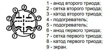
In order to understand correctly the opening of the lower lamps (information for those who earlier did not have the right lamps), it is necessary to turn the lowers to yourself and the key down (the sector without the lowers), then the miraculous look that you put in front of you, you will see the pictures of the pins of the lamps (application for other lamps). As you can see from the little one, there are two tripods in the lamp, but we need only one. You can beat the odds, no matter what, there is no difference.
Now we follow the scheme to the right. Coils of inductance L1 and L2 are best wound on a deep round base (mandrel), ideally for which a medical syringe with a diameter of 15 mm is suitable, and L1 should be wound over a cardboard tube, as it falls over the body of the syringe with a small susilla, so that it is safe to regulate. As an antenna to the extreme visnovka L1, you can solder the pieces to the dart, or solder the antenna to the nest and vikoristovuvat more seriously.
L1 and L2 should be wound with a dart to increase the quality factor, for example, with a dart 1mm and more with a 2mm crochet (special accuracy is not needed here, so you can especially not fool around with a skin coil). For L1, it is necessary to wind 2 turns, and for L2 - 4-5 turns.
Far away to go capacitors C1 and C2, yakі є dvuhsektsiynym condenser zminnoї єmnostі (KPE) s repeated dielectric, vіn є іdealnym rіshennyam for podіbnih circuits, KPI with solid dielectric vikoristovuvatysya nebazhano. Напевно, КПЕ є рідкісним елементом даної схеми, але його досить легко знайти в будь-якій старій радіоапаратурі або на барахолках, хоча його можна помітити і двома звичайними конденсаторами (обов'язково керамічними), але тоді доведеться забезпечувати підстроювання за допомогою імпровізованого варіометра (приладу for smooth change) of inductance). KPE example:

We need only two sections of KPI and stench obov'azkovo to be symmetrical, tobto. mothers have the same capacity for regulation. The contact of the dry part of the KPE will be the most accurate.
Let's follow the next line of fading on resistors R1 (2.2MΩ) and capacitors C3 (10 pF). Їx value can be changed at small boundaries.
Coil L3 plays the role of an anode choke, tobto. high frequency is not allowed to pass far. Pіdіyde be a choke (only not on a flooded magnetic circuit) with an inductance of 100-200 μH, but it's easier to wind a thin enameled copper rod on the body of a refined strain resistor 100-200 turns.
Capacitor C4 serve as a stand-alone warehouse at the output of the receiver. Headphones or podsilyuvach can be plugged in without intermediary to nogo. Yogo's amnesty can change at the end of great boundaries. Bazhano, so C4 will be plivkovym or papery, but with ceramic tezh will be practiced.
Resistor R3 is a potentiometer of 33 kOhm, which serves to regulate the anode voltage, which allows you to change the lamp mode. It is necessary for more precise tuning of the mode for a specific radio station. You can replace it with a resistor, but it's not necessary.
On what element have they skinned. Yak bachite, the scheme is already simple.
І now trochs from the drive of life and installation of the priming machine.
Anodne eating can be safely brewed from 10V to 30V (it can be more, but it’s not safe to connect low-ohm equipment there). The strum is small there, and for eating pidijde BP, be it tightness with the necessary tension, ale bazhano, schob vin buv stabilizovaniya and mav minimum noise.
And even more obov'yazkovoy umovoy є kharchuvannya razzharennya lamps (in the picture with the pinning of the wines of the designations as a heating), to that without a new won it is not pracyuvatime. There are already more streams needed (300-400 mA), but the voltage is only 6.3V. If you change 50Hz, then the voltage is constant, moreover, it can be from 5 to 7V, or rather, vikoristovuvat canonical 6.3V. Especially I didn’t try vicoristovuvati 5V on roasting, but shvidshe will be fine for everything. The voltage is applied to the legs 4 and 5.
Now about installation. Ideally, the expansion of all elements of the circuit in a metal case is connected to the earth at one point, but it is also possible to use it without a case. Since the circuit works in the range of UHF, all the connections at the high-frequency part of the circuit are due to be as short as possible to ensure greater stability and capacity of the robot. Axis stock of the first prototype:

Everything worked out for such an installation. Ale with a metal case-chasі trohi stable:

For such circuits, hanging installation is ideal, because it gives good electrical characteristics and allows you to make corrections to the circuits without any special difficulties, which is not so easy and neat to get out of the board. Wanting and my installation can not be called accurate.
Now schodo nalagodzhennya.
After that, you 100% messed up in the correctness of the installation, applied the voltage and didn’t vibrate and didn’t jump out of anything - it means that the circuit works better for everything, because the correct ratings of the elements are correct. And you, better for everything, you will feel the noise in the headphones. If you don’t forget the stations at all positions of the KPI, and you’re sure that you have received movement stations on other outbuildings, then try changing the number of turns of the L2 coil, or you will change the resonance frequency of the circuit and you can spend it on the band. І try turning the knob of the change resistor - you can help. Although it does not help anything, you can experiment with the antenna. At what point does the renaissance end.
At this stage, everything has already been said, but it is presented more nevmila rozpovid can be supplemented with advancing rollers, which illustrate the tricks at different stages of development and demonstrate the quality of yoga robots.
Purely lamp option (on a breadboard level):
Option from the addition of ULF to IMS (already from the chassis):
In the remaining version, the lightness of the troch was spent, to that the IMS was fixed. It seemed to be the only solution, that at the anode 20V in the ULF mode, the other triode didn’t work for me, although I might need the mode and є, but I didn’t know.
Yak ULF buv vikoristany pіdsilyuvach PAM8403, which live in the form of a linear voltage stabilizer L7805 (among the people it is called a roll, after the name of the radian analogue).
The plans for the development of this project include the creation of one more super-regenerator on a 6s6b lamp, but also a portable one, shards of a lightly mother's portable lamp.
Dyakuёmo for respect. Ready comments on questions on the topic.
PS: This attachment generates a lot of power for an hour of work and viprominyuє їх through the antenna, tobto. overgenerator can create a reshkodi, guard it.
Jerela:
1. Super-regeneration
2. Superregenerative primer
3. Documentation for the lamp 6n23p
4. Tutorsky "Simply amateurs transmitting and receiving UKKh" 1952