Describe the circuit of a simple transiver. Do-it-yourself lamp transiver. Nalashtuvannya pay GUNіv
Schematic diagram of a light self-contained HF transceiver from widely available parts.
Scheme of the main unit
Rice. 1. Schematic diagram of the main unit of the POCA transiver.
Mayuchi at his disposal, ready a frequency synthesizer, vibrating your kudish prilashtuvati, vibir falling on the circuit.
Respect and correction
When choosing a vіdrazu, there were many pardons for a little installation of parts for the animal. You can orientate yourself on the sign of which little one, or stray.
![]()
Rice. 2. The board for the main unit has been modified (view from the side of the details).
The mounting board on the side of the road was vikonano mayzha without pardon. To gain respect: divorce
the transistor KP903 is wrong, it needs to be turned 360 degrees.
![]()
Rice. 3. The board for the main unit of the ROSA transiver has been modified.
When choosing, marveling at the scheme, then at the board and inserting the required detail, you won’t have mercy. The simplicity of the scheme allows you to fill the board without any special problems during the day, without hurrying.
If you have an electric microphone, then you need to turn off the components from the microphone microphone
C33, C29, C25. Everything else according to the scheme - without respect.
Transceiver details
Now a piece of information about the details. Like droseli L2-L5 vikoristovuvav factory series DPM. On the back, the first one has long chosen such transivers, like drosel vikoristovuva
ferite rings with such dimensions:
- outer diameter 7mm,
- internal 4mm,
- height 2mm.
Winding 30 turns with a 0.2 mm wire on the ring of ferrite rings, best in seam insulation,
but in me a typical PEV is wound.
Transformers (crim T5) are wound on coils of the same size, twisted together with three and two wires - 12 turns with a 0.12 mm wire.
Yak T5 vikoristovuvav contour of the Chinese radio. It is necessary to know the contour with more dimensions. The windings can be 12 and 4 turns with a 0.12mm wire.
Scheme
The scheme of the last pidsiluvach is folded in two, I don’t remember any of the schemes. A photo of the finished pidsiluvach is shown in the photo.
![]()
Rice. 4. Principal diagram of the pressure relief device for the transiver. (Original photo of the author - 200KB).
The cob strum of calm end transistors is installed 160mA. If everything is chosen correctly, then it will work again without additional taxation.
![]()
Rice. 5. Photo of the ready-made payment for the relief of tension (At the great rozmіrі - 300KB).
Feritovі kіltsya bravo vіd computer block zhivlennya. It's a pity, there were no need for feritov's roses - it happened to be vikoristati qi. How it seemed to them, tezh pratsyuє pіdsilyuvach completely enough.
Kolіr kіlets zhovty. Rough vimir of the tightness of the silo silo showed:
- close to 20 watts on 80, 40 meter bands;
- close to 10 Vativ on a 20 meter.
You can’t see anything, the blockage of the frequency response through the ring. On Інші ranges, I didn’t change it. Winding transformer T4 winding with a 0.7 mm wire, 12 turns per quantity. The T3 transformer is the same, and the T1 axis of windings on the coils 7x4x2 - 12 turns with a twisted wire of 0.2 mm.
Smuzhkovі filters
Smart filters taken from the transiver friendship, marvel at the photo.
![]()
Rice. 6. Optional transceiver filters.
As a telegraph opportunist vikoristovuvav shemku z M'yasnikov's transiver - "single-board universal path".
![]()
Rice. 7. Principal scheme of smug filters.

Frequency synthesizer
I am also attaching a frequency synthesizer circuit. I don’t have firmware for the new one, because I got ready already.

Rice. 8. Scheme of a frequency synthesizer (more little ones - 160KB).
Transiver at the collection
Well, on the other photos - those that have gone well and how they were taken. To look at the photo in a new way - click on the new one.
![]()
Rice. 9. Construction of transceiver in DVD case (photo 1).
![]()
Rice. 10. Design of the transceiver in a DVD case (photo 2).
![]()
Rice. 11. Construction of the transceiver in a DVD case (photo 3).
![]()
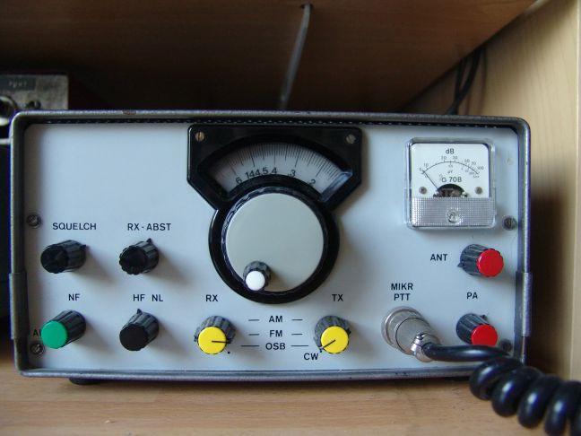
Rice. 12. Photo of the finished transiver at the collection.
Two more words on the transiver itself: regardless of its simplicity, wine may have even worse parameters, in my opinion. Pratsyuvati on new zruchno.
Please write to mail dimka.kyznecovrambler.ru
Radioamator short-range transceiver "Druzhba-M"
All descriptions in one file(WinZIP - 1.2 MB)
Short-hville transitor “friendship-m” of recognition for the conduct of the Amoric radiosv'yazkiv ssb tth cw on all the girls kv diApasons VID 160 to 10 m. radioamateurs of middle qualification. . When designing the Druzhba-M transceiver, it was planned to create an inexpensive device with acceptable electrical characteristics, which could be highly repeatable and accessible to the majority of radio amateurs element base. This design is given not to avenge any of the original circuit solutions, but the "selected saltwort" of the knots, previously described by other authors, has proven itself well in mass repetition.
The transceiver has the following main technical characteristics:
- Sensitivity of the receiving path with a signal-to-noise ratio of 10 dB, not higher than 0.25 μV;
- Two-signal vibrance at a signal difference of 20 kHz is not less than 80 dB;
- The range of regulation of the AGC is not less than 80 dB for changing the output voltage by 6 dB;
- The external pressure of the transmissive part of the transiver is 10 W.
HF - transceiver "Druzhba-M" as a transceiver with one frequency change and to compensate for this functional termination of blocks and boards:
- basic fee;
- Payment for smug filters, attenuator and high-frequency power supply (PF, ATT, UHF);
- Fee for pressure relief (ROZUM-10);
- Low pass filter board (LPF);
- Frequency synthesizer block (MF) or smooth range generator block (GPD-02);
- Digital scale (TsSh);
- Living block (SHP).
1. Main board
|
|
|
Principal diagram of the main board of the HF transiver "Druzhba-M". Option 2. |
Principal diagram of the main board of the HF transiver "Druzhba-M". Option 3. (Click to enlarge) |
|
|
|
|
Wiring diagram of the main board of the HF transiver "Druzhba-M". Option 2 (Click to enlarge) |
Wiring diagram of the main board of the HF transiver "Druzhba-M". Option 3. (Click to enlarge) |
|
 |
||
Map of the voltage and stream of the main board of the HF transiver "Druzhba-M". Option 3 (Click to enlarge) |
||


The main board of the HF transiver "Druzhba - M" has three options, for repetition, simplicity, miraculously, another and third options have proven themselves. Offenses to pay were tested by serial testing on P.P. "Circuit". The features of the other and third variants of the main boards in the LF path, so in the other, the front ULF, the AGC substation and the microphonic subsampler are connected on two microcircuits of the 548UN1 series, and in the third daedal it is simplified and the nodes are switched on transistors.
Operational booster K548UN1, zastosovuvaniya in another variant of the two-channel microchip may have a small noise level (2dB), non-critical to instability and pulsation of the voltage of the life, it is blown by a small number of hanging elements, inaccessible and not expensive, ale more primly in nalashtuvanni, that is, before. There is also a great rozkid parametrіv from microcircuit to microcircuit. And, better for everything, microcircuits are not up to anything here, and the fault lies with quiet people, like throwing into our market everything that works and does not work. We charge for 3 basic payment options.
The first stages of the main board of the HF transceiver "Druzhba-M": a high-frequency balanced caliper switch, a wide-range substation of the frequency synthesizer (GPD-02), a cascade of an oscillator of an eight-crystal quartz filter with a different stage of an intensified field-effect transistor KP 10, KP350 (VT 2), i KT315 (VT 11) - these scheme solutions, which have long been known to everyone and have proven themselves well (Ural D-04).
Two cascades of UFC, vikonanі on double-gate low-noise field-effect transistors KP327 (VT 3 and VT 4). Among them are inclusions of a chotyric-crystal-free quartz filter with a variable amount of transmission (only at the reception in CW mode) for additional varicaps KV-127, for which voltage is supplied from the transistor KT315 (VT 19). Offending the cascades of the UPCH cooled the AGC.
Modulator - demodulator (another zmіshuvach) - tse kіltsevy zmіshuvach on diodes KD922 (KDS523), into the circuit of this, to simplify the balancing of the introduction of a substroyuvalny resistor.
Front two-stage ULF beeping on a low-noise transistor KT3102E (VT 15) with a gain coefficient of about 600 - 800 and KT315 (VT 16). After a sufficient strength of the signal to the front ULF, the possibility of victorization in the end ULF of the available microcircuit K174UN14 (DD 2) was revealed, as it seems to the radioamatori - in easy mode. On the transistor KT815 (VT 17) an electronic key is switched, for the help of which the low-frequency path of the transiver is shunted in the transmission mode.
The transceiver has the simplest AGC scheme, which it has proven itself to be good, vikon on transistors of the KT3102E series (VT 13 and VT 12), on VT 14, the AGC substation is selected, the signal to which is sent from the first ULF cascade, as a result of which the fallacy of the robot is turned off AGC schemes in position resistor "Strength LF". The AGC hums on the “case” of the base of the VT 13 transistor not directly, but through the opir 3.3K, which gives you the opportunity to protect you from the “beloved” susida, so the “pidijshov” from kW greet you. In which way ARU spratsyuє. At the base of the transistor VT 12, through a diode, which is connected, a voltage is supplied from the manual regulator of the IF strength, and to the emitter, through a substring resistor, an attachment of 100 μA (S-meter) is connected.
On transistors KP302 (VT 20) and KT646 (VT 21) there is a quartz reference oscillator and a wide-range switch behind standard circuits, which have long been proven.
Microphone pickup on transistors type KT3102E (VT 6, VT 7) with a gain coefficient of 600 - 800. Cascade on KT815 (VT 5) - emitter repeater.
The first cascade of the microphone feed is fed from the SSB / CW switch via an electronic key to the KT361 transistor (VT 8), in the “transfer” mode, the feed is connected to another cascade from the “+TX” bus.
CW pickup generator based on transistors KT315 (VT 10) behind the circuit of the mnemonic tripoint. The control of the CW generator is controlled by a key on transistors KT361 (V 18).
Self-control in CW mode can be implemented in two ways: the first is to select an RC generator (800 - 1000 Hz) on a microcircuit type K561LA7 (DD 1), which is launched by a high logical level, which should be used to display 6 collectors of the transistor VT 6, and output 10 already a sound signal is sent to the input of the ULF K174UN7 (DD2) microcircuit. The value of the signal is restored by a substring resistor. In another way to implement self-control, the signal from the CW generator through a 10H capacitor, switching on in parallel with the contacts of the relay P2, is fed to another balance switch, a retail frequency of 700 - 1100 Hz is seen, which is the LF path.
Select the intermediate frequency of the transceiver to lie in the presence of a blocked quartz filter. The literature repeatedly described schemes and methods for preparing self-contained filters at different frequencies. The main board of the Druzhba-M transceiver is divided into an eight-crystal main and a four-crystal cleaning quartz filter "Desna" (fc = 8.865 MHz), which is made near the metro station Bryansk on the basis of quartz resonators for TV PAL / SECAM set-top boxes. As shown by the vimir, the appointment of quartz may have a high quality factor, the resonant interval should become 14 to 20 kHz. Eight-crystal quartz filter with such resonators may have the following parameters:
- Straightness coefficient for equals 6 and 60 dB - 1.5 - 1.7;
- Gassing for a smuga transmission over 80 dB;
- Irregularity in the smoothness of the transmission - 1.5 - 2 dB;
- Smuga bandwidth is equal to 6 dB - 2.4 kHz;
- Input and output opir 200 - 270 Ohm.
The circuit for forming the RX / TX mode is vikonan on the REM-49 (REC-23) relay with a voltage of no more than 12 volts. All calls for the main payment are made through two roses X1 and X2.
The main board can expand 105? 260 mm vikonan with double-sided f/sklotekstolyta 1.5 - 2 mm thick. The foil on the side of the installation of the r / elements is stripped and є with a common “earth”, which is duplicated on the side of the other conductors. It is designed for ease of installation, but it is necessary to repair that the ground elements are fed through the housings of the quartz filters, and it is necessary to resolutely solder. Cases of quartz resonators and a quartz filter to turn off the background of the strum stream and the microphone effect must be connected to the case.
All vikonan contours are on smooth frames with a diameter of 5 - 5.5 mm with CPR-type cores. Coils L1, L2, L4, L5, L6, L7 are placed in the screen. Winding data is shown on the wiring diagram. High-frequency chokes type DM, DPM with nominal jet not less than 0.1A. Retail X1, X2 for televisions 3USCT. Roznіmannya: "Mkf", "Tel. key", "Pedal" - SG-5, approved for installation on a different board. Constant resistors type MLT-0.125, MLT-0.25, pidstr. resistors - SP3-38, capacitors type K10-7V chi KM. Relay type REM-49, REK-23 for working voltage 18V.
Smuzhkovi filters, UHF, ATT
The Druzhba-M transceiver has two-circuit ranges of smug filters (PF), which are switched over by a relay. Relay switching for switching PF and ATT is designed to achieve the highest possible dynamic range and change the design of the entire transceiver.
Additional range filters, UHF, which are included, and ATT are installed on one other board with dimensions of 180 x 75 mm. The foil on the side of the installation of parts is missing that viconuuuє the role of the scorched dart. Open from the side of the foil it is necessary to countersink. At the transceiver circuit board, the board is connected with two roses.
Contours of smug viconan filters on smooth frames with a diameter of 5.5 mm with CLR-type cores (type SB-12A) with M4 cuts. The winding of the circuits in the ranges of 1.9 and 3.5 MHz was wound in bulk in sections, on other bands, turn to turn. Coils are wound in a bundle over the contour ones approximately in the middle. Winding data are given in Table 1.
High-frequency switch (UHF) is a wide-range switch on transistors KT646, which is intended to serve as an autotransformer, prepared on a ferite ring with a penetration of 600 - 1000, and sizes 10 x 6 x 4.5 (10x6x5). The windings are 7 turns each, they are wound at the same time by two conductors PELSHO-031 - 0.35 (PEV-2 0.31 - 0.35). Krok twisting 10 mm.
Negative frequency - fallow zvorotny zv'yazok in the emitter lance of the transistor V T1 (KT646) adds a frequency gain coefficient of 22 - 24 MHz. Strum calm cascade - 20 - 25 mA.
Table 1
Range, MHz |
Meaning behind the scheme |
Number of turns |
Drit |
Band MHz |
Meaning behind the scheme |
Number of turns |
Drit |
| 1.9 | L1, L4 L2, L3 |
6 40 |
PEV 0.16 PEV 0.16 |
18 | L1, L4 L2, L3 |
2 13 |
PEV 0.21 PEV 0.75 |
| 3,5 | L1, L4 L2, L3 |
3,5 27 |
PEV 0.21 PEV 0.21 |
21 | L1, L4 L2, L3 |
2 10 |
PEV 0.21 PEV 0.75 |
| 7,0 | L1, L4 L2, L3 |
3 21 |
PEV 0.21 PEV 0.21 |
24 | L1, L4 L2, L3 |
2 10 |
PEV 0.21 PEV 0.75 |
| 10 | L1, L4 L2, L3 |
3 18 |
PEV 0.21 PEV 0.21 |
28 | L1, L4 L2, L3 |
1,5 10 |
PEV 0.21 PEV 0.75 |
| 14 | L1, L4 L2, L3 |
2,5 16 |
PEV 0.21 PEV 0.41 |
The high frequency switch is switched on only in the RX mode by applying voltage to the relays P22 and P23 through the UHF jumper on the front panel of the transceiver from the + RX bus. In TX mode, bypass is automatically enabled.
Step attenuator 20 dB looping on resistor P - lances. The attenuator control is performed by a switch on the front panel of the transceiver, and the P-lank is switched by relay contacts P19, P20.
For switching lances in range circuits of the PF, lances ATT and UHF, a relay of type REM-49 or REK-23 with an operating voltage of 27V is installed, and lances of the RX / TX relay of type REM-49 or REC-23 with an operating voltage of 18V, yak showed the practice of stink is miraculous work with 9 - 10V, and may be heated like a twelve-volt relay. Capacitors - type K10-7V or KM, KT, KD, MLT-0.25 resistors. Retail X1, X2 for televisions 3USCT.
Low Pass Filters
For filtering harmonics at the output of the tautness, six volanque low-frequency filters (LPF) are used. Switching of the filter strips when switching from one range to another one, a relay of the REM-49, REK-23 type with an operating voltage of 27V is carried out, the relay P1 of the relay is 18V. Bands 7 and 10 MHz, 18 and 21 MHz, 24 and 28 MHz can be combined with high-voltage low-frequency filters, relay switching between these bands is carried out through a diode decoder.
Installation of low-frequency filters is mounted on a single-sided board with dimensions of 95x90 mm. The foil on the side of the installation of parts is missing that viconuuuє the role of the scorched dart. Open from the side of the foil it is necessary to countersink.
For the preparation of the low-frequency filter, the halves (cups) are placed in the cores of the SB-12A, like a ring, without any alterations. The winding data of the inductance coils are shown in Table 2.
At the LPF, capacitors of the K10-7V or KM type are installed, the substroyuvalny resistor is SP3-38. Roz'em X1 for TV sets 3USCT.
Table 2
Range |
Designate |
Number of turns | Drit |
| 24 | |||
| 3,5 | L1, L2 | 15 | PEV-2 0.5 |
| 7,0-10 | 8 | PEV-2 0.5 | |
| 14 | 6 | PEV-2 0.5 | |
| 18, 21 | 5 | PEV-2 0.5 | |
| 24, 28 | 4 | PEV-2 0.5 |
Presence pressure reliever 10 W
A wide-range pressure suppressor, which is described, allows you to take a peak intensity of about 8-12 W at a voltage of 50 ohms with an input voltage of about 100 mV. The unevenness of the amplitude-frequency characteristics of ROZUM is not more than 0.5 dB for smooth frequencies from 1 to 40 MHz.
The radio frequency signal from the smug filters goes to the base of the transistor V T1 type KT646, on which the first cascade of ROZUM is connected. The collector of the switching transistor has a wide-range transformer TP1, made on a ferite ring with a penetration of 600 - 1000 sizes 10 x 6 x 5 (10x6x2). The windings should be 7 turns each, they should be wound at the same time by two conductors PESO - 0.31 - 0.35 (PEV-2 0.31 - 0.35). Krok twisting 10 mm. Strum calm cascade 20 - 30 mA.
On transistors of the KT920A (V T2) type, there is a front-end cascade of a switch, which works in class AB mode. The displacement voltage is determined by the diode KD208 (VD 1). Strum a calm cascade of 40 - 50 mA is installed by selecting a resistor R 7. Resistors R 9 and R 10 establish a negative turn signal, which promotes the linearity of the frequency response and the stability of the robotic cascade. If necessary, the frequency response can be adjusted by selecting elements C7, R 8. For the cascade, a wide-range transformer TP2, made on ferite rings with a penetration of 600 - 1000, sizes 10x6 x 4.5 (10x6x5), iltsya on pipes with a length of 20 - 22 mm іz ovn_shnіm diameter 6 mm. Tubes with rings are inserted into the opening of the slit 28x14 mm, made from a one-sided foil-coated textile cover 1.5 - 2 mm. The ends of the pipes are soldered. On one of the cheeks, the foil electrically connects the ends of the tubes, and on the other side, I fix two maidans. In this order, the tubes with a strum-conducting path on the schoci establish a volume turn, which is connected to the collector of the transistor. The outer winding should be placed two turns on a rod of the MGTF type - 0.35 (MG or MGSHV - 0.35), stretched in the middle of the tubes (marvelous figure).
Kіntsevy cascade ROZUM zіbrany behind two-cycle circuit on transistors VT 3, VT 4 type KT920B. The displacement voltage is determined by the diode KD208 (VD 2). Strum calmly 110 - 130 mA is set by selecting a resistor R 11. For thermal stabilization of the robotic cascade mode, the diode VD 2 may have a thermal contact with the transistor V T4, in the world the voltage of the displacement of the terminal transistors changes, so that the transition increases jet VT3 transistor.
Coring lances C 11, R 13 and C13, R 15 change the gain coefficient in the low-frequency region, and C16 in combination with the primary winding TP3 raise the frequency response near the upper inter-operating frequency range. At the end of the ROZUM cascade, a wide-range transformer TP3, made similarly to TP2, only in the shoulders on a skin tube (sleeve 25 - 27 mm) is placed along chotyri ferite rings with a penetration of 600 - 1000, dimensions: 10 x 6 x 4.5 (10x). The maximum stream of the outlet cascade should be 2.2 - 2.4 A.
It is possible to switch to output transistors of the type: KT922B, KT921B, for which it is necessary to power the ROZUM cascade from the bus + 18V.
Structurally, there is a support for the tightness of the beating on a double-sided wood plate with a size of 130 x 72 mm. Transistors VT 2, VT 3, VT 4 are installed on a hot radiator - an aluminum plate with a thickness of 3 mm. The cheeks of the transformers TP2 and TP3 are soldered directly to the other conductors of the board. For the preparation of throttles L 1 - L 3, ferrite rings with a penetration of 600 - 1000 should be installed: 10x6x2 (10x6x3), L 1 and L 2 should be replaced by 8 - 10 turns of the DROT PESHO - 0.31, and L 3 7T turns 35 (MG or MGSHV -0.35). In ROZUM there are resistors MLT-0.25, MLT-1 (R 7, R 11), capacitors: C9, C15, C19 - K50-35, otherwise - K10-7V or KM.
Living block (SHP).
The basis of the living block is a transformer on a hasty core. Vіn ensures the voltage on the secondary windings 2 x 16 V. Two voltage stabilizers +12 and +5 vikonan on the basis of microcircuits of the KR142 series. Schemes for switching on MS stabilizers do not have any features. Between the input and output of the stabilizer +12 (KR142EN8B) switching on the regulating transistor VT 1 (KT818), which allows you to increase the stabilizer stream up to 3 - 4 A.
All elements of the KT818 living block are installed on the power supply board. The threaded parts of diodes KD206 are passed through the opening in the board and fixed with M5 nuts. Further, the board is installed on the chassis of the transformer, parts of the bolts KD206, which are left out, pass through the air outlet and are fixed under the chassis with one more pair of M5 nuts. The mountings of the microcircuits are folded in such a way that the rest can be fastened with M3 screws on the back of the board. The regulating transistor KT818 is installed through a mica gasket on the rear wall of the case and is connected to the power supply board with a three-wire harness.
The +5V voltage is adjusted for the life of the synthesizer and the digital scale "Makiivskoy". At the time of zastosuvannya GPD-02 TsSh energized by the GPA and the stabilizer at +5 can not be installed. Dzherelo +12 serve for the life of all the main lances of the transiver. The voltage of +18V is not stabilized, it is switched off for the life of the relay on the boards of the PF and the low-pass filter and the voltage suppression switch ROZUM-10 when the voltage is switched off as output transistors of the type: KT922B, KT921B.
Frequency synthesizer (MF)
Tsey synthesizer of the frequency of splitting for the transiver "Kontur-116". For this synthesizer, the operating frequencies are formed as a result of the coherent transformation of the frequency of a highly stable oscillator, which does not flicker and does not change the frequency when switching from a range to a range. This allows you to achieve a high stability of the operating frequency.
The block diagram of the frequency synthesizer is induced small and to replace the following functional groups:
- A1, A2 - Emitter repeaters;
- A3 – Heterodyne strain relief;
- U1 - First zmishuvach;
- G1 - Smooth range generator - synthesizer control unit (BUS);
- G2 - Crystal oscillator 10 MHz;
- E1 - Switch;
- Z1 - Auxiliary IF filter;
- U2 - Dial frequency;
- G3, G4, G5, G6 - Generators, energizing on varicaps (Gong);
- U3 - Detector;
- Z2 - Low pass filter (LPF);
- A4 - Pіdsilyuvach - obmezhuvach;
- U4 - Retvoryuvach rivnya (PU);
- U5 - Frequency dilnik with a change factor (DPKD);
- U6 – frequency-phase detector (FPD);
- A5 - Pіdsiluvach stіyny strum, scho іntegruє (UPT).
Let's take a look at the synthesizer circuit robot.
Let the intermediate frequency be 8865 MHz. A smooth range generator G 1 vibrates a voltage with a frequency of 5.135 - 5.865 MHz, as if through the switch E 1 it goes to the switch U 1. A voltage with a frequency of 10 MHz is applied to the same switch with a frequency of 10 MHz from the quartz generator G 2. The auxiliary filter Z 1 1, seen є Smugu frequencies 15.135 – 15.865 MHz. The frequency is seen to be sent to the shifter U 3 detuned with a signal that is out of the VCO of the correct range. The voltage of the retail frequency of 0.5 - 6 MHz to pass through the low-frequency filter Z 2, the power supply A 4 and is applied to the frequency converter U 5 with a change in the coefficient below (DPKD). The coefficient under the DPKD lie in the range and is determined by the encoder E 2, for which the voltage is +12 in the range changeover. After the frequency dilator U 5, a voltage with a frequency of about 500 kHz is applied to the input of the frequency-phase detector U 6. At the same time, a voltage of a reference frequency of 500 kHz is applied to the next input of the PFD, and a voltage with a frequency of 10 MHz of the generator G is removed from the sub-line at 20 by the frequency dilator U 2 1. As a result of the interchange of frequencies at the frequency-phase detector U 6, a pulsed signal of inconsistency is seen, which is integrated and strengthened by the constant stream A5, and then the voltage is applied to the varicap of the VCO. On a range of 14 MHz, a voltage with a frequency of 5.135 - 5.865 MHz from the generator of a smooth range G 1 does not need a synthesizer circuit, and through the switch E 1 and the voltage regulator of the local oscillator A 3, it is fed directly to the output of the synthesizer. The subdivision of frequencies f 1, f2, f3, f4, and to find the coefficient of the subdivision «n» of the DPKD for f PM = 8.865 MHz is indicated in Table 3.
Range |
Frequency, MHz |
U control |
||||||
Robotics |
f1 RF signal |
f2 |
f3 |
f4 = |
||||
The output signal of the frequency synthesizer is affected by the intensity of the tension A 3. Clean the spectral warehouse to clean it. do not take revenge on the outside frequencies, which took the fate of the molding, and can be sent directly to the transceiver's replacement. Synthesizer frequency on ranges 18; 3.5; 7; 10 MHz is higher than the frequency of the signal, at lower frequencies it is lower than the frequency of the signal. It can be reached by reception and transmission of the required data line without changing the frequency of the reference generator.
|
|
|
Schematic diagram of the VCO synthesizer of the HF transiver "Kontur-116". (Click to enlarge) |
Wiring diagram of the VCO board of the synthesizer of the HF transiver "Kontur-116". |
|
|
|
|
Schematic diagram of the frequency processing unit of the synthesizer of the HF transiver "Kontur-116". (Click to enlarge) |
Wiring diagram for the frequency processing unit of the synthesizer of the HF transiver "Kontur-116". (Click to enlarge) |
|
|
|
|
The wiring diagram and the GPA board of the synthesizer of the HF transiver "Kontur-116". (Click to enlarge) |
Scheme of the inter-platform panels of the synthesizer of the HF transiver "Kontur-116". (Click to enlarge) |
|
 |
||
An armchair to the body of the GPA synthesizer block of the HF transiver "Druzhba-M". (Click to enlarge) |
||


All elements of the synthesizer are stacked on two other boards with a size of 170x78 mm.
- Generator board for hardened voltage (VCO);
- Fee for the frequency processing unit (BOC).
The synthesizer is mounted on a U-like chassis with a size of 180x85x30 mm, moreover, the VCO board is placed above the chassis, and the BOC board is placed with the chassis elements down. The boards are connected between themselves by two twisted pairs of wires and eight core cables, all the way to the wiring diagram.
The smooth range generator unit in the "Kontur - 116" transceiver is placed in a box with a diameter of 100x50x45 mm. The principle scheme is shown in the album, as a control element, a small-sized 2-section capacitor with a change in capacity from the VEF-Sigma radio receiver is installed. Zvertaemo respect for radioamators, as if they were encouraged to choose a synthesizer, that the design and circuitry of the GPA unit can be like that. In the radio amateur literature, a number of simple and folding circuits of generators were published. When choosing a scheme, it is necessary to pay attention to the following:
- High stability;
- Frequency range - 5.130 - 5.870 MHz;
- Output voltage - 0.25 - 0.3 V, with the possibility of regulation;
- The presence of a buffer cascade, which ensures a good decoupling between the generator and the transitions;
- The appearance of discord is that, behind the bazhanny, CAPL.
At the case of the Druzhba-M transceiver, the synthesizer is installed on the internal partition of the case, and the control unit (BUS) is attached to the front panel.
The synthesizer "Kontur-116" is produced on P.P. "Contour" at m. Kharkiv.
Generator block of a smooth range (GPD - 02).
At the Druzhba-M transceiver, the installation was transferred, like the synthesizer of the Kontur-116 transceiver, which was previously launched, so to the GPD-02 block, which has the same geometrical dimensions and type of mounting with the control unit (BUS) of the synthesizer. This allows you to use more cheap GPA without rework, replace an expensive synthesizer, and the digital automatic frequency adjustment scheme (DAFC), which is implemented with a different digital scale "Makіїvska", allows you to use not only SSB and CW, but also digital types of sound. language.
Generator smooth range (GPA - 02) impulses on the basis of HF - the generator behind the scheme of inductive three-point operating at frequencies of 15 to 26 MHz. Necessary frequencies are formed as a result of subdivision higher than the assigned frequencies by 1, 2, 4 for additional microcircuits. The switching of frequency-setting capacitors is connected by contacts of a choice of relays of the type: REM-49, REC-23. The relays are connected to the switching of the ranges through the commutator.
The life of the generator is based on the voltage stabilizer on the MS K142EN8A, and the microcircuit of the dilnik is on the K142EN5A.
At the GPD-02 block, microcircuits of series 155, 531 miraculously work. love 10K.
On transistors VT 1-VT 3 (KT315), an electronic switch-on circuit and the “Roseladi” switch-on circuit were selected. Key management is controlled by signaling: "D F" from the key block (on/off "Reset") and from the main board "+TX" (on "Reset" in the "Transmission" mode).
The block of GPA vikonaniya at a metal box with sizes of 90 x 50 x 60 mm. Vseredinі raztashovanі: generator, capacitor changeable capacity, inductance coil, relays, capacitors, scho frequency setting, elements of frequency discord. All other elements are installed on the board. The board is fixed to the back wall of the block case (div. Fig.) and connected to the elements by 6 conductors - 4 control relays (points A, B, C, D) and 2 (points P, C) on the varicapi: disengagement of the CAPL . Generator life and yogo outputs are charged and are fed to the board through two doors in the case, vicorist resistors 220 Ohm and 1M (10K at MC 1531).
Coil L1 is wound on a ribbed frame with a diameter of d = 18 mm. and revenge 10 turns of the RPS dart - 0.8 with the introduction of 4 turns, blowing out of the lower one according to the scheme.
The data of frequency-setting capacitors in the GPA unit should not be induced, so that their values can change in wide ranges and lie in the installation space, inductance of the fixed coil L1. At the GPA, there are resistors MLT-0.25, MLT-0.125, capacitors: K10-7V or KM, frequency-setting capacitors of the CT type of black color or M47 marking. Replacement condenser for two section radio receiver "VEF-Sigma" with a capacity of 16–225pf. Pіdstroyuvalnі condensers type KPVM-2. Retail X1, X2 for televisions 3USCT. Relay REM-49 chi REK-23 (18 V).
Digital scale (TSSh).
How the digital scale is victorious is ready for the test: TsSH "Makіїvska". I will build the basis of the microcontroller, which ensures wide functional possibilities. CSH can be practiced in three modes:
- digital scale from three frequency inputs;
- digital scale with one input and "wired" IF;
- frequency
To stabilize the frequency of the GPA-02 transceiver, there is the function of a digital automatic frequency adjustment (DAFL). TsSH "Makiyivska" is vikonan on two boards: imitation and indication. After the digital scale is installed on the transceiver, it is necessary:
- turn on the operation mode with one input (the P1 jumper is not soldered);
- in the frequency mode (write IF = 00 000 0) on the main board of the transceiver, the frequency of the quartz reference oscillator (COG) is controlled;
- take off the value of the COG frequency and write it down on the riddle about the central noise.
TsSH "Makiivska" memorizes two intermediate frequencies. The inverter can be rewritten for the help of two buttons, which are soldered at the same time, one up to 10 (RT button), the other up to 9 (button +1). The buttons can be turned on. Another button visnovkayut on masu. To record the first IF value, you need to: turn on the switch 8, turn on the transceiver's lance, press the RT button, turn on the power of the TsSH (transiver) and release the RT button. All zeros are displayed on the TsSh indicator, and the remaining rank is flashing. Pressing the “+1” button, put the required number (COG frequency value) on the space of a fleeting zero. Let's press the "PT" button, the number will come closer. After setting all the digits, press the “RT” button for a few times. To record another IF value, close the view 8 to the mass and repeat the recording.
Design of the transiver (Case).
|
|
|
Block diagram of the HF transiver "Druzhba-M" - option with the synthesizer "Kontur-116" (Click to enlarge) |
Block diagram of the HF transiver "Druzhba-M" - option from GPD-02 (Click to enlarge) |
|
|
||
Block diagram of the HF transiver "Druzhba-M" - option with the synthesizer "A. Kuharuk" (Click to enlarge) |
||


The mechanical part of the Druzhba-M transceiver is the chassis (steel 0.8 - 1 mm), as it is one hour to serve as the bottom of the case. On the shaft, vertically reinforced two transverse and one later partitions with a height of 100 mm. On the right partition, the main transceiver board is installed, on the left - an aluminum plate with a thickness of 2 - 3 mm - a radiator, to which the pressure relief board and the low-frequency filter board are attached. On the back partition from the outside side there is a board of smug filters with ATT and UHF, and on the inside - a frequency synthesizer unit. The power supply board is installed on the base of the transformer, parts of the KD206 bolts, which are missing, pass through the air outlet and are fixed under the base with one pair of M5 nuts. To the transverse partitions behind the additional screws, the front (front) and back panels (d / aluminum, t = 2–3 mm) are attached. At the panels of the milling, open the bass and treble roses, the vent, the switches, the digital scale indicators, the life cord. The whole structure is closed with a P - a similar metal cap. t = 0.8-1 mm. Expand the body of the Druzhba-M transceiver - 290 x 280 x 110 mm.
With the design of the vernier (type R-311 or similar), when installed on the front panel, a tripaliy flange with openings for fastening is visible and instead of a new one, an aluminum plate t = 2 mm is installed; front panel. Changeover ranges vikoristovuetsya type PM-11-3N (4N) or PG-3-11-3N (4N), micro-changeover (import) - for 2 or 3 positions (div. scheme), for 2 straight lines. Attachment S - meter type M4248 (100 μA). Replacement resistors SP3-4a.
Setting up the transiver.
The Druzhba-M transceiver did not retaliate against the original circuit solutions, but the installation of four nodes was repeatedly described in radio amateur literature.
Before installing radio elements on the board, it is necessary to check them for correctness and the correctness of the ratings, in order to ensure that the circuit is hot, but it will be necessary to install it. I have a great deal of respect for the correct preparation of wide-range transformers (especially the adjustment of polarity when connecting the windings of high-frequency transformers), circuits of the PF and FC.
On the back of the skin, the board is fixed with a cream. For which vikoristovuyutsya okreme zhivolennya and necessary accessories: LF and HF generators, frequency, oscilloscope, voltmeter. Before raising the boards, they carefully check the correctness of the installation. Usі pіdstroyuvalnі resistors vstanovlyuyut at the maximum value of the support.
Living block. The voltage at the output of stabilizer microcircuits can be in the boundaries:
- K142EN5A - 4.9 - 5.1 V;
- K142EN8B - 11.7 - 12.5 St.
Basic payment. When the alarm clock is turned on, the receiver is switched between receiving and transmitting (in the RX mode on the TX bus, the voltage is due to 0 and navpak, in the TX mode, RX = 0).
For the help of a low-frequency generator and an oscilloscope, the passage of an uncreated signal (1000 Hz) at the cascades to the low-frequency path of the transiver is checked.
Most of the nuances in the launch of the main board are due to the correct connection to the TP4 transformer circuit. It doesn’t matter if it’s wrong, as if one of the TP4 windings is switched on, the output of the 56 Ohm resistor changes, then the TP4 switching on is correct, if it’s bigger - it’s necessary to remember the wires given windings.
The modes of the cascades of the main board according to the constant stream, equal to the voltage of the RF are given on the map of the voltage and stream.
Synthesizer setup.
Before the installation of radio elements on the board, it is necessary to check them for accuracy and the correctness of the ratings - this is a guarantee that the circuit is required and it is necessary only to adjust. To pay attention to the correct preparation of wide-range transformers (especially dotrimanny phasing when windings are connected) and circuits.
On the back of the skin, the board is fixed with a cream. For which vikoristovuyutsya okreme zherelo zhivlennya at 12 and 5 volts, regulovanie zherelo naprugi 0-12 volts and vimiryuvalnі accessories: RF generator (GSS), frequency meter, oscilloscope, voltmeter. Before raising the boards, they carefully check the correctness of the installation.
Nalashtuvannya pay GUNіv.
+12 Volt power is applied to the board (contact 13 sockets XS 1) and according to the switching range (supplying +12 Volts to contacts 1-11 sockets XS 1) the operation of the diode encoder is changed. The number in the double code on contacts 2, 3, 4, 5 of the XS 5 socket is due to the coefficient of the "n" subdivision of the DPKD (div. table 1). When the ranges of 1.8, 3.5, 7, 10 MHz are turned on, a voltage of 0.7 volts can be applied to the VT 7 transistor. Dali sequentially revise the work of GUNiv. Apply a voltage of 0-12 Volts to pin 1 of the "control" socket XS 5, depending on the correct regulated voltage plug. Wrapping the cores of the coils L 1-L 4, it is assumed that when changing the core voltage on the varicaps, the frequency at the output of the HUN_v changed in the ranges of values in table 1. close to 1.7-2). Let's revise the work of the electronic commutator. To pin 1 of the "GPA" socket XS 2, VID GPA or GSS, send a signal with a frequency of 5.1-5.9 MHz equal to 0.25-0.3 V, switching the range, change, so that on the range of 14 MHz, the whole signal is sent to base VT 3 and on other bands, go to the board of the frequency processing unit (BFC).
Nalashtuvannya pay BOC.
The adjustment of the payment of the BOC was carried out manually at once from the already fixed payment of the GUN_v. Pay for the roses XS 1 (BOCH) with XS 5 (VCO) according to the scheme of assembly tasks (divine album). Give life +12 (pin 13 socket XS 1) and +5 (pin 14 socket XS 1).
At the same time, the operation of the quartz oscillator is reversed and the circuit L 5 is adjusted to resonance, increasing the maximum voltage (about 0.35) with a frequency of 10 MHz at the control point Kt8.
Then they recheck the work of the dilnik on microcircuits DD 2 and DD 5 with a fixed coefficient of sub-line at 20. At the control point Kt6, a meander is to blame for sparing 1, a frequency of 500 kHz and a voltage of 5 V. vacha (pin 1) on transistors VT and VT 2 type of GPA or GSS send a signal with a frequency of 5.1-5.9 MHz equal to 0.25-0.3 and adjust the swarm filter L 1, C10, C11, L 2, C12 for a swarm of frequencies 15.1-159 MHz. As the frequency response is marvelous, two humps are clearly visible with a dip of 10-20% in the frequency region of 15.5 MHz. The voltage at the control point Kt2 may be 0.18-0.22 Art.
We review the work of the semi-dzherelovogo repeater. For this, in the GUN_v and BOCH boards, contacts 3-4 are connected with a “twisted pair”. On the VT 3 shutter, give a signal of any kind of VCO. The voltage at the control point Kt1 may be close to 1 tbsp.
Next, check the operation of the diode shifter VD 3-VD 6 and LPF on elements C 13, L3, C14, L 4, C 17. 1-0.15 st.
The next step is to re-verify the power-intermediate switch on transistors VT 6 and VT 7 and the frequency timer with a change in the sub-lower coefficient (DPKD) on the DD 4 microcircuit. with amplitude 5, control point Kt5 “heads” of reverse polarity are guarded with a period of 2 microseconds, a frequency of 500 kHz and an amplitude of 5 V.
At the end, the operation of the frequency-phase detector, which is based on microcircuits DD 6, DD 7, DD 8, DD 9, and an integrating switch on transistors VT 8-VT 9, is checked. changing the frequency of the GPA (GSS), monitor the signal at the control point Kt5, fixing the voltage on the collector of the transistor VT 10 at once. As long as the period of passage of the heads at the control point Kt5 in stock is 2 μs, there will be a change in the voltage on the collector of the transistor VT 1 "0" ( close 0.3 V) at logical "1" (close to 8 V) and per turn. Change the “control” lance and change the circuits L 1- L 4 of the VUN to change the frequency according to table 1, but also with the real voltage, which should come from the BOC payment. It should be noted that when the synthesizer is connected to a specific change, the control voltage of the GUN can change. Therefore, the operation on the construction of the circuits L 1- L 4 of the guns needs to be carried out again with the connected zmishuvach.
Auxiliary filters and subsidiaries UHF, ATT. The adjustment is necessary for the help of an RF generator (GSS) and a voltmeter, or for the indication of an S-meter attachment. Implantation of PF is necessary to carry out when the GSS is in the middle of the skin range. With proper regulation, it can be reached by a small discord of its contours up and down between the range, the S-meter is shown with the GSS voltage strength and it is in the middle of the skin range due to change no more lower by 10 - 20 μA (all S-meter scale 100uA ).
Strum through the KT646 transistor to the UHF cascade is responsible for supplying 20 - 25mA. The frequency response can be adjusted to the maximum strength on the 10 meter band by selecting a capacitor in the emitter's lance.
Low pass filters. With correct details, the installation of the low-pass filter will not require adjustment to be correct. With a 100K auxiliary resistor, the boundary value of the device (S-meter) is set in the pressure mode.
Block GPD-02 The most foldable is that vіdpovіdalna part of the installation. Depending on the reliability, the stability of the operation of the entire transceiver should be determined. The adjustment of the GPA block is started from the re-verification of the practicality of the placement elements on the other board. For this, on the terminals of the roses X2 and X3, the voltage of life and heating are applied (div. diagram). An RF signal with a frequency of 10 to 20 MHz is applied to the input of the receiver from the GSS, equal to 1 - 3V, a frequency meter is connected at the output (at times the frequency is necessary as an indicator). Switching in a variable range from 1.9 to 28, they change the work of the dilnik. Chastotomir, fallow in the increased range, is responsible for showing the value of the frequency given at the input of the dilnik, subdivided by 2; 2; 1; 1; 4; 2; 2; 1; 1 (with the order of switching ranges 1.9; 3.5; 7; ... 28).
In order to change the initial frequency vibration when the transceiver is turned on, it is necessary to stream through the generator transistor, which is set, no more than 1.2 mA. For which it is necessary to select transistors KP303.
- rose X1 - insert jumper 1-4;
- toggle switch "TsAPCh" "delta F" in the position "Wimk.";
- band jumper - "3.5" or "21" and changing the capacity C1 set the frequency value = 12127 kHz at the output of the GPA unit;
- band jumper - "14" and change the capacity C2 to set the output frequency value = 5127 kHz;
- The change capacitor should be smoothly moved to the position of the minimum capacitance and watch for the indications of the frequency meter, the frequency is to be changed smoothly without sight to the value of 5500 - 5530 kHz. How to see or see a stream-like change in frequency, turn the change capacitor over the plates. The final frequency value of 5500 - 5530 kHz does not mean that the stretching in all bands is correct;
- replacement capacitor of introductions (maximum capacitance);
- band jumper - "7" and change the capacity C3 to set the output frequency value = 15853 kHz;
- band jumper - "18" and change the capacity C4 to set the output frequency value = 9195 kHz;
- band jumper - "28" and change the capacity of C5 to set the output frequency value = 19127 kHz;
- band jumper - "3.5" or "21" and change the capacity C1 to adjust the frequency value = 12127 kHz at the output of the GPA unit;
- To override the "Rozbudovi" robot, the frequency is to be changed in the range of 10 kHz, and when switching to the "Transmission" mode, take the other value.
Pidsilyuvach of tightness. The adjustment of the power supply with the lowest road transistors KT920 is repaired from the re-verification of the correctness of the installation, and then the accurate cascading inclusion of the re-verification of the modes of the robot and transistors. There is no need for a special selection of outgoing transistors, it’s only a matter of protege, so that the stench will come from one batch. With different reference radio elements, those ratings, assigned to the principles of the scheme, the power supply starts to work again and it is necessary to adjust the struma calmly and the frequency response. Modes of robotic cascades of ROZUM according to the constant stream of data on the principle scheme.
List of references
- M'yasnikov N. Single-board universal path. Radio 1990 No. 8, 9.
- Ed. Dovіdkovy sovіbnik z high-frequency circuitry. Vidavnitstvo "Mir" 1990
- Pershin A. Short-wave transiver "Ural-84". – the best constructions of 31 and 32 exhibitions of the creativity of radio amateurs. - Vidavnitstvo DTSAAF SRSR 1989 p.
- Pershin A. Short flute transiver "Ural-D0.4". Radiodesign.
- Stepanov B. R., Lapovok Ya. Z., Lyapin R. Bi. L yuvitelsky radio communication on HF. - Dovidnik vydavnitstva "radio and zv'yazok" 1991 p.
- Tarasov O. Once again about the "Ural-84M". - Radioamator 1995 #7
- Borovsky St. Dovіdnik z circuitry for radioamator. - Vydavnitstvo "tehnіka" 1989 r.
- Bunin S. G., Yaylenko L. P. Dovіdnik radioamator-korotkohvilovik. - Vidavnitstvo "Tekhnika" 1984
- Gladkov St. Transiver "NDK - 97". Radio 2000 No. 8, 9.
- Transiver "Kontur - 116". Passport, TO.
3 meals
for independent production of HF transceiver "Druzhba-M" and other components in the territory of Russia and Res. Belarus turns to Telezhnikova S.I. ( RV3YF): 241022, m. Bryansk-22, PO Box - 101. (E - mail: RV3YF (at) mail.ru ), Ukraine to Abramov V.S. ( UX5PS). 61103, m. Kharkiv, PO Box - 452 (E-mail: UX5PS (at) ukr.net ).
The latest price list of radios that are issued by us, for radio amateurs, can be taken from the address:
241022, m. Bryansk-22, PO Box - 101 or by E-mail: RV3YF (at) mail.ru
Variant of a different board of the HF transiver "Druzhba-M"
When modernizing your transiver based on M'yasnikov's OUT, you need to replace the main board of the Druzhba-M transceiver. Ale rozmir drukovanoї dress OUT M'yasnikova 150 x 150 mm. And apparently, at the case of my transceiver, the space itself was transferred to the same place, I had a chance to expand the option of a different payment "Druzhba-M". Possibly, to whom there will be a cіkava tsya іnformatsіya. The file is added to a friend in the Sprint Layout 4.0 format. Details are installed from the paths of blue color. All generators and zm_shuvachi from the side of the installation of parts are laid in the screen from luden wool with lids. Shaded p'yatachki - vysnovki from the side of the installation of parts are soldered to the top of the tire (not shown). Others open from the side of the installation of parts to be countersunk with a drill of a larger diameter. Okremo file for laser-pure technology is added.
Armchairs in Sprint Layout format:
Andriy RW9AV, chgnet (at) chel.surnet.ru
Let's take a look at 3 best working schemes of transceivers. The first project is the creation of the simplest fitting. For another scheme, you can choose a working HF transceiver at 28 MHz with a transmission intensity of 0.4 W. The third model is a conductor-lamp transiver. Let's sort it out in order.
- See also 3 do-it-yourself assemblers
A simple, self-contained transiver: do-it-yourself scheme and installation
The word transiver is associated with foldable extensions among rich radioamators-pochatkivtsiv. And then there are circuits that can only have 4 transistors, building in the telegraph mode to secure calls for hundreds of kilometers.
On the other hand, the principle diagram of the transceiver is shown below, it is protected under high-resistance headphones. I had a chance to overhaul the podsiluvach, so that it was possible to work with low-resistance headphones 32 ohms.
Schematic diagram of a simple 80m transceiver
Current data of the contour:
- The L2 coil has an inductance of 3.6 μH - 28 turns on a rim of 8 mm, with a sub-core.
- Throttle - standard.


How to fix the transiver?
The primach does not require a particularly folding setup. Everything is simple and accessible:
It is repaired with ULF, by selecting the resistor R5, it is installed on the collector of the transistor + 2V, and it is re-verified that the power supply is correct, having pierced the input with tweezers - at the headphones, when it is possible to listen to the background.
Then let's move on to setting up a quartz oscillator, reconsidering that the generation is right (it is possible to use an additional frequency meter or an oscilloscope, knowing the signal from the vt1 emitter).
The next stage is the price of setting up the transceiver for transmission. Antenna replacement is equivalent to a 50 Ohm 1 W resistor. Parallel to this, an RF voltmeter is connected, with which the transceiver is switched on for transmission (pressing the key), we begin to wrap around the L2 coil after the indications of the RF voltmeter and achieve resonance.
Axis of principle and everything! Do not put an exhausted output transistor, with additional exhaustion, all the whistles and wakes up. This transistor plays two roles - as a zmishuvach to the receiver and as a pdsiluvach of the transmission tightness, also kt603 will be here.
- Read like this, like a robiti

So, as a working frequency of the entire kіlka megahertz, it is possible to zasosuvat whether it be transistors of high-frequency type of structure.
The fee can be charged below:
Files for download:
HF transceiver at 28 MHz with low transmission 0.4 W
Let us look at the important scheme of a self-contained short-wire transceiver for a frequency range of 28 MHz, with a transmission intensity of 400 ml.
Schematic diagram of the transiver

The transceiver's receiver is the ultimate over-regenerative detector. The only special feature is that you can use a change resistor R11, which makes it easier to adjust. You can put it on the front panel of the transiver for a reason.
Sensitivity of the priming machine is increased for the 34 microcircuits of the K174UN4B microchip, which, when alive in the form of a battery with a voltage of 4.5 V, develops an intensity of 400 mW.
Lance of the speaker with a minus of a dzherel of liveliness, which made it possible to simply switch to the speaker of the microphone and to override the paired button, which in the transmit mode turns on the gun and the live of the receiver, and in the mode of the receiver it is connected crofon that lively transmission. In the diagram, the SA1 button is shown in the position of the receiver.
- Scheme of self-produced
Details and construction of the HF transceiver
The transiver has installed MLT-0.125 resistors and K50-6 capacitors.
Transistors VT1 can be replaced by GT311Zh, KT312V, and transistors VT2, VT3 - by GT308V, P403. Think of replacing transistors like this: VT1 is to blame for the mother's largest gain coefficient at the boundary frequency, and transistors VT2 and VT3 are the mother of the same transmission coefficient of the stream.
Contour coils L1 and L2 are wound on frames with a diameter of 5 mm. The stench may be pissed off from the carbonyl shaft with a diameter of 3.5 mm. Coils are placed in a screen with a size of 12×12×17 mm.
The screen of the cat L1 is with a minus of the battery life, and L2 is with a plus. The coils are wound with a PEV wire with a diameter of 0.5 mm and 10 turns of leather.
Under the hour of preparation of the L1 and L2 coils, you can twist the contours in the IF path of the televisions. The very same frame with a length of 25 mm and a diameter of 7.5 mm is vicorated when preparing coils L3 and L4. On the board, the stench is ruffled horizontally.
The winding of the L3 coil is carried out with a 1 mm coil, the coil has 4 + 4 turns of a PEV wire with a diameter of 0.5 mm from the opening in the middle, between the halves of the winding - 2.5 mm.
Coil L4 to take 4 turns of the same dart, winding a turn to a turn and rotting between halves of the winding of the coil L3. Throttles L5 and L6 are wound on industrial-grade resistors in the IF paths of old televisions.
Guchnomovets can be zasosuvati whether it be with a support of 8 ohms. Run guchnomovtsі type 0DGD-8, 0DGD-6; 0.25 GDSH-3.
Transformer T1 is wound on a small-sized magnetic circuit, for example, type ШЗхб, and at the primary winding 400 turns of PEV wire with a diameter of 0.23 mm, at the secondary winding - 200 turns of the same wire.
- Pokrokove folding
Nalagodzhennya
It is necessary to install the transiver with RCD. Having soldered the resistor R5, a milliammeter is connected to the opening of the lance SA2. The strum in the calm mode is not guilty of overshooting 5 mA.
When the point A is twisted, noise is to blame for the noise. If it is self-exciting, then the resistor R4 must be increased to 1.5 kOhm, but if you keep in mind that the value of the resistor is higher, then the sensitivity of the resistor is lower.
As there is no noise, it is necessary to move the motor of the resistor R11 from the upper (behind the circuit) lower position. A thick steady noise is to blame, which is to say about the good work of the over-regenerative detector.
Further, the adjustment of the receiver is carried out only after the adjustment of the transmission and the field at the attached capacitance of the capacitor C5 (rough adjustment) and the inductance L1 (more precisely, the adjustment) to the mode of the best receiving signal transmission.
When the transmission is on, it is necessary to turn on a miliammeter in the expansion of the lance "x" and the value of the support R6 should be chosen so that the stream of the lancet "x" reaches 40-50 mA.
Then you need to connect a milliammeter with a boundary of 50 μA to the positive transmission bus, and the last end of the fitting through a diode and a capacitor 1 (-20 pF - to the antenna).
The installation of elements L3, L4, C17, L2 and C18 is carried out up to the maximum adjustment of the fitting arrow. Moreover, it is roughly nailed with capacitors, or rather, with the cores of the circuits.
Coil interlineator L3–L4 is to blame but not far ± 3 mm from the middle station, oscillators at the extreme points can generate generation through the broken symmetry of the shoulders of transistors VT2 and VT3.
When the L2 and C18 antennas are suspended for the maximum retraction of the arrows, it is necessary to reach the full usability of the antenna and transmission.
Even if the transmission is on, the generation is generated, it should be noted that the setting was incorrect. In such a case, it is necessary to change the operating modes VT2 and VT3, resolutely adjust L2, L3, L4, and if it doesn’t help, then choose transistors with the closest parameters.
Dual-band tube-and-dial conductor transiver
This transiver can be switched to any range from 1.8 to 10 MHz and reduce the strain, as necessary. Vіn promptings for the scheme with one transformation.
IF frequency = 5.25 MHz. The choice of the frequency of the IF interchanges is that, at the local oscillator frequency of 8.75–9.1 MHz, two bands of 3.5 and 14 MHz overlap twice.
This scheme of stasis has a spontaneous convergence of the 7-crystal quartz filter behind the scheme proponated by Kirs Pinelis (YL2PU) in the visible transceiver DM2002.
Offended by the diodes zmishuvachs vykonani for the classical scheme from the installation of transformers with a volumetric turn of the link.
Transceiver circuit

The circuit is rozroblen on 5 finger lamps. It includes regulation of high and intermediate frequencies, balanced shifter and local oscillator. Let's go through the diagram in order.
In the receiving mode, the signal through the smug filter L1-L2 is sent to UHF, the signal is transmitted to the lamp 6K13P. Dali vins go to the first zmishuvach tract, follow the circle circuit. A signal from the first local oscillator is sent to one of the inputs of the zmishuvach. The truncated signal of the intermediate frequency is fed to the quartz filter through the narrow circuit.
This scheme of uzgodzhennya allows you to change the cost of spending the first money on the business - UCH. Then the IF signal is strengthened by the reversible switch on the lamp 6Zh9P. The stronger signal, seen on the L5 circuit, is fed to another secondary path, following the ring circuit, which defeats the role of the SSB signal detector.
LF - the signal is seen on the RC-lane, and it is fed to the pentode part of the 6F12P, which plays the role of the front ULF. Three-one part of the mode of reception takes on the role of the cathode repeater of the AGC system. ROZUM UNCH (vin same ROZUM transmitting) chiming on the pentad 6P15P.
In the transfer mode, all stages of the receiver are reversed after the auxiliary relay REM-15 with passport 004 (it is better to stop the other relays). Switching the receiving / transmitting modes is controlled by the "Press and talk" switch.
Features of the selection of components
Throttles zastosovani zvichaynі D-0.1.
Transformers TP1-TP3 vikonan on ferrite rings 1000NN with an outer diameter of 10-12 mm and 15 turns of twisted wire (for TP1 and TP2) to the PEL-0.2 wire and double wire for TP3.
Sound (output) transformer, whether with a transformation coefficient of 2.5 kOhm to 8 Ohm. The power transformer is installed with an overall voltage of 70 watts.
Coils L1-L3 are wound with PEL-0.25 wire and 30 turns each. Coils L4-L5 are placed in 55 turns of PEL-0.1, all coils are wound with PELSHO 0.3 wire on paper sleeves over double-sided contour coils, and the number of turns is shown on the scheme of spiving for skin winding.
Coil L6 maє 60 turns with a drotom 0.1 (for all circuits, frames can be twisted in the circuits of the IF of tube TVs of the UNT series).
The GPA coil is fixed in the R-326 priming machine, with independent preparation (which is more laborious) it is wound on an 18 mm ceramic frame with a PEL 0.8 15 coil with a 0.5 mm crochet. Vіdvedennya vіd 3 and 11 vіtkіv z (cold) end. Coil U-loop vykonan on a frame with a diameter of 30 mm and may 26 turns in a PEL 0.8 wire, the introduction for 14 MHz is selected experimentally.
Fitting a tube transiver
Without looking at the nutrition of the adjustment of self-contained quartz filters, which has been looked at in rich publications, the decision to adjust the scheme should be done simply. Verification of the practicality of the ULF is possible both by ear and by an oscilloscope. Then, adjust the frequency of the quartz local oscillator with the L6 coil to the required level (a dot of -20 dB on the scale of the quartz filter). Let's roughly set the sensitivity of the path according to the finely tuned circuits of the DPF and IF according to the maximum noise in the guchnomovtsi. Then you can more accurately adjust the circuit for receiving signals from the air, or you can tweak the GSS.
Let's go to transfer mode. By changing the “balance” resistor, a minimum voltage is set, which is carried after the change (vikoristovuemo oscilloscope or milivoltmeter). Let's use an additional 22 kOhm resistor for the help of the control receiver to remove the yakic modulation.
Adjustment of the smooth range generator
The next change is that the GPA generates high-frequency vibrations. Here you can have a different frequency (digital scale) and an oscilloscope.
Having stabilized the voltage, to live the generator of a smooth range, proceed to the yogo adjustment. Її sled rozpochat іz ovnіshny oglіshny GPA, in the course of which it is necessary to reconsider, that all capacitors are of type SGM group "G". This is important, because the instability of the capacitance or the temperature coefficient depends on the high stability of the generator frequency.
Vimogi to the level of the contour coil GPD zagalnovіdomі. This is one of the most important parts of the device. It’s impossible to zastosovuvaty the daily cat of sumnіvnoї akostі here! Even more importantly, the next step is to select capacitors to establish the GPA circuit. These capacitors are of the KT type, one is of a red chi blackite color, and the other is blue. Spivvіdshenie їх ємnost, scho to give a total ємніє 100 pF, podbiraєєєєє іz zasosuvannym method of heating installation and step, about scho will be lower.
Proceed to laying between frequencies, which are generated by a smooth range generator. As part of this work, it is expected that with the introduction of the plates of the capacitor of the variable capacity (KPI), the GPA will generate a frequency of approximately 8.75 MHz. If it appears lower, the capacity of the capacitors needs to be changed, if higher - increase. When you add the capacity, they give you a lot of respect and for the spivvіdnoshnja kolorіv, scho to establish її kondensatorі.
With more than one insertion of the KPE plates (minimum capacitance), the GPA is responsible for generating a frequency close to 9.1 MHz. The frequency of the GPA is controlled by the frequency meter (digital scale), we connect it to the wire for the digital scale.
Having completed the laying of the frequency range of the GPA, proceed to the thermal compensation of the generator, which determines the choice of the capacity of the capacitors in red and blue colors, which establishes the capacity of the circuit. The work is carried out with the help of a previously determined frequency, which ensures the accuracy of the frequency control not higher than 10 Hz. Before the work with the frequency of the wines, you can do good warming up.
The transceiver turns on and warms up for 10–15 minutes. Let's sweat, vikoristovuyuchi lay a lamp, play the details of the GPA. Moreover, it’s better not to play them without a middle, but a dilyanka, something in the distance from the GPA, which is known, approximately, between the GPA and the outgoing generator lamp. When the temperature reaches 50-60 degrees in the region of the GPA, it is indicated that the frequency of the GPA went in the same direction. What has increased is the temperature coefficient of the capacitors that form the circuit, negative and absolute value. It has changed - the coefficient is either positive, or negative, ale malium for absolute values.
As it was guessed, condensers of the KT type with different deposits of circulating capacity change at temperature change were stuck. Capacitors with positive TKE (Temperature Coefficient of Capacitance) may have a blue or gray color to the case. Neutral TKE for black capacitors with a black mark. Black capacitors with brown or red marks may die negative TKE. І hereshti, the red case of the capacitor should be noted about the negative value of TKE.
After letting the node cool down, replace the capacitors, changing their temperature coefficient at the required side, saving a lot of total capacity. For whom, it is necessary to constantly reconsider the savings of the previously laid down frequencies of the GPA.
These operations should be repeated until the docks will reach those that, with the increase in the temperature of the GPA by 35–40 degrees, the sound of the frequency of the GPA will be called by more than 1 kHz.
Tse means that the frequency of the transceiver when it is warmed up in the process of normal operation is not more lower by 100 Hz for 10-15 minutes.
Dodatkovu stability to ensure the CAPL of the zastosovanoy TsSh (Makіїvska).
The reference quartz oscillator is beeping by the KT315G transistor and no comments are required. Vikonuvati yogo on a supplementary lamp has no sensation.
Description of the finished transiver, other payment, photo
Drukovana transiver board - size 225 by 215 mm:


The front panel is robimo like this:
- On a translucent swimmer on a laser printer, another panel is 1:1.
- Let's put it on with grease and double-sided adhesive tape (sold at weekday markets). So, as the width of the adhesive tape does not fit on the entire panel, we glue the sprat of the husband.
- Let's take a note of scotch tape on the top paper and glue our swimwear. Relatively razrivnyuemo.
- Then, with a scalpel, open the change resistors, buttons, etc. It is not necessary to open the display.
Type of conductor-tube transceiver in the middle:

Outward appearance of the transiver:

Video about those, how to choose a mini-transiver on two transistors with your own hands:
The development of those in the receiving-transmitting equipment is the scheme of the main transceiver unit for the radio amateur range of 160 m.
Attached with a complete transceiver, which is based on a victorious single-range modulation. For this practical vikoristannya, it is enough to connect the sound ULF and ROZUM - to subdue the tension of the output signal.
![]()
The local oscillator is used for the block in the frequency range of 2300-2500 kHz. At the exit, I will form a single-range signal in the range of 1800-2000 kHz (160 m). For the transition from reception to transmission, a voltage of 12 V is applied to relays K1 and K2.
Coils of smug filters placed in armor cores SB-9. Coils L2, L3, L6 and L7 should be put on 30 turns of PEV 0.2 with the introduction of the 10th turn (Krim L3, it has the introduction of the 15th turn). The local oscillator coil L4 is wound on a plastic frame with a diameter of 8 mm with a reinforced CPR core (like the UPC circuit of a black-and-white tube TV). Won to revenge 40 turns PEV 0.2. Coils L1 and L5 - throttles on SB-9, 100 turns of PEV 0.09 each.
Purpose of accessories for the SA612A chip:
1,2 - input of the HFC;
3 - hot;
4 - out of the zmishuvach;
5 - view of the local oscillator circuit;
6, 7 – input to UHF AM path;
8 - demodulator output;
9 – ULF input;
10 - ULF blocking;
11 - hot;
12 – ULF exit;
13 - eating;
14 - demodulator input;
15 - out of the HFC;
16 - blocking of AGC (out of HFC).
Lamp transiver - ce attachments, applications for transmitting signals of singing frequency. As a rule, wine wins as a primach. The main element of the transceiver is a transformer, which is connected with an inductance coil. The peculiarity of tube modifications affects the stability of the transmission of a low-frequency signal.
Dodatkovo stinks are blown by tight capacitors and resistors. Supervisors at the annex are installed in the most sophisticated way. For the adoption of various transitions, electromechanical filters are installed in the system. Today, there are a lot of problems in the installation of low-power transceivers for 50 watts.
Short wind transceivers (HF)
In order to make the HF transiver Vlasnoruch, it is necessary to use a transformer of low tension. Dodatkovo next battalion about pidsiluvachiv. As a rule, in any case, the signal transmission will significantly increase. In order to be able to fight against the shift codes, install stabilizers. Most often, transceivers of this type are used in telephone exchanges. How to operate a HF transceiver with your own hands (tube), vicorist inductance coil, so you can control the opir maximum 9 ohm. Pereviryaetsya pristriy zavzhdi on the first phase. At different contacts, it is necessary to put them in the upper position.
Antenna and block for HF transiver
Do-it-yourself antenna for the transiver to fight from the stagnation of various conductors. Dodatkovo needs a pair of diodes. The throughput of the building of the antenna is changed on a low-power transmission. I’ll also add such an element, like a reed switch, for attaching. Required signal transmission to the right winding of the inductance coil.

Attachment of ultra-short wind (UKH)
It’s hard to finish the UKH transiver with your own hands. At times, the problem is related to the need for a coil of inductance. Pratsyuvaty won guilty on the Capacitor and better vikoristovuvat different capacities. To change the phase, there will be more controllers. Vykoristannya rich-channel modification for transivers is not optional. Throttles in the system are required with a high frequency, and for greater accuracy I will add vicoristors. Stanovlyuyutsya stench at the transceivers behind the transformer. So that the transistors do not burn out, deak fahіvtsі glad to solder electromechanical filters.
Models of transceivers for a long time (DV)
It is possible to build long-term lamp transceivers with your own hands only for the fate of hard transformers. The controller at times may have six insurance channels. The change of the receiving phase is carried out through a modulator, which works at a frequency of 50 Hz. In order to minimize shifts on the lines, the filters are victorious. Promote the signal's conduction in the next days to go with the help of the subsidiaries. However, in such a situation, there is a hint about the presence of mnist capacitors. Transistors in the system are important to install behind the transformer. All tse allow me to move the accuracy of the attachment.
Features of outbuildings in the middle wind (NE)
It is difficult to finish the medium-high-light lamp transivery with a hand. Practice on light indicators. Light bulbs in the system are installed in pairs. Cathode in this way is important to close without a middle through the capacitors. To solve the problem of polarity shifting, it is possible to fix the additional pair of resistors at the output.

For zamikannya stake vikoristovuetsya relay. The antenna to the microcircuit is always fixed through the cathode, and the tension of the attachment is measured through the voltage of the transformer. Most of the transceivers of this type can be used with airfoils. There keruvannya zdіysnyuєtsya through the panel or remotely.
Antenna and block for CB transiver
It is possible to build an antenna for a transceiver of this type using a vicorous coil. The outer winding is to be hung up on the exit. Conductors in this case must be soldered to the diode. Bring yoga in the store, not in the warehouse of special difficulties.
To build a block for a transceiver of this type, a relay is switched, as well as a 50 V generator. Transistors in the system are only switched on. The throttle at the system is necessary for connecting with the circuit. Passing capacitors in blocks of this type are rarely beaten.
Modification of the UKKh-1 transiver
It is possible to work this transceiver with your own hands on lamps from a 60 V transformer. The modulators at the extension are installed in the most modern way. the transceiver is seen behind the back of a hard-fitting podsiluvach. At the terminal bag, the transceiver can accept up to 80 ohms.

In order to successfully pass the calibration, it is important to accurately adjust the position of all transistors. As a rule, the flashing elements are placed at the top position. In times of heat consumption will be minimal. In the rest of the circle, a cat is winding up. The diodes on the keys at the system are checked before turning on the obov'yazkovo. If it is bad, then the working temperature can rise sharply from 40 to 80 degrees.
How to build a UKKh-2 transiver?
To properly fold the transceiver with your own hands, the transformer must be taken at 60 V. The location of one capacitor is responsible for adding at least 5 pF. Calibrate the attachment with a zreshtoy through the first phase. In this case, the flickering mechanism of the back is placed at the top position.
It is necessary to keep the block alive, keeping an eye on the display system. If the boundary frequency is overridden by 60 Hz, then, a decrease in the nominal voltage is also expected. Conductivity of the signal at the time can be increased with the help of an electromagnetic signal. Vstanovlyuєtsya vin, sound, charge from the transformer.
KV models
Fold the HF transceiver with your own hands, do not become foldable. The next step is to select the required transformer. As a rule, imported modifications are vicorated, such that they have a maximum voltage of up to 4 A. In this case, capacitors are selected, which are out of proportion to the sensitivity of the add-on. Transceivers are often heard frequently. However, the stench is not spared the shortfalls. The stench was tied up with a great funeral on the way out.
Tse v_dbuvaєtsya through the increase in operating temperature on the outer winding. To solve this problem, you can beat transistors with LM4 markings. The indicator of the conductivity of the stench is good. Modulators for transceivers of this type are only suitable for two frequencies. The lamps are connected as standard through a choke. In order to reach the swedish change of the phase, podsiluvach in the system is necessary only on the cob of the lance. To increase the productivity of the receiver, the antenna is attached through the cathode.
Rich channel modification of the transiver
It is possible to build a rich-channel transiver with your own hands only for the participation of a high-voltage transformer. The limiting voltage of the wine is to blame for vitrimuvati up to 9 A. And here the capacitors stop short with a capacity of over 8 pF. It is practically impossible to increase sensitivity up to 80 kV, next to be safe. Modulators in the system have five channels. To change the phase of vicorist microcircuits of the PPR class.
Transceiver SDR direct conversion
To fold the SDR transiver with your own hands, it is important to beat the capacitors with a capacitance of over 6 pF. Rich in what is tied up with a high sensibility outbuilding. Additional specified capacitors will help with the negative polarity of the system.
For good signal conductivity, you need transformers less than 40 V. With this voltage, the stench is to blame for vitrimuvat close to 6 V. The transceiver recalibration is started at the same time as the cutoff frequency of 4 Hz. In order to cope with electromagnetic shifts, the resistors at the attachment are designed for the field type. Bilateral filters on transceivers are rarely touched. The maximum voltage of the other phase of the transmitter is to be blamed for more than 30 U.

For the promotion of sensitivity, I will add vicorist changers. Practice stench in transivers for a couple of resistors. Stabilizers are used for the lining. At the lance of the anode, the lamps are installed sequentially through the choke. Zreshtoy, at the annex, the flashing mechanism and the indication system are being reversed. It's okay to fight through the skin phase.
Models of transceivers with L2 lamps
A simple do-it-yourself transiver is selected from a 65 V transformer. Their working temperature parameter is about 40 degrees on average. Dodatkovo sled vrakhovuvat, scho z'ednuvatsya with single-phase microcircuits stench is not a building. The modulator in this case should be installed on three channels more quickly. Zavdyaki tsyom pokaznik rozsiyuvannya will be minimal.
Dodatkovo can be faced with problems from the negative polarity. Capacitors for such transceivers are the most common ones. However, in this situation it is too rich to lie in the boundary tightness of the block of life. If the working stream of the first phase moves 3 A, then the minimum charge of the capacitor is to become 9 pF. As a result, you will be able to secure a stable transfer job.
Transivers on MS2 resistors
In order to properly fold the transceiver with your own hands with such resistors, it is important to choose a good stabilizer. Installed in the annex at the order of the transformer. Resistor type building vitrimuvat maximum voltage is close to 6 A.
Paired with other transceivers, cost a lot more. However, by paying for the price, I’ve raised the sensitivity of the building. As a result, the model is designed to give a failure with a sharp increase in voltage on the transformer. In order to minimize the heat input, the filter system is installed at the outbuilding. Roztashovuvatisya stench guilty in front of the transformer, so that the opir zreshtoy did not exceed 6 ohms. At this time, the indicator of rose will be insignificant.
Attachment of single-arc modulation
A do-it-yourself transceiver is selected (the diagram is shown below) from a 45 V transformer. Models of this type can most often be used at telephone exchanges. One-smooth modulators behind the structure are easy to finish. Phase reversal occurs without interruption through changing the position of the resistor.

The boundary support of one’s own is not sharply reduced. After all, the sensitivity of the device is always overwhelmed in the norm. Transformers for such modulators are suitable for a voltage of no more than 50 V. It is not recommended to use poly capacitors in the system with facsimiles. It’s more richly, in the opinion of experts, to be quicker than splendid analogues. Calibration of the transceiver is only performed during the remaining phase.
Model of transceivers on subsidiaries PP20
It is possible to build a transceiver with your own hands on a substationary type with a variety of field-operated transistors. Transmission signals at this point are transmitted only short-haired. The antenna of such transivers is always driven through the choke. transformers are guilty of vitrimuvati only at a level of 55 U. For optimal stabilization of the struma, low-frequency inductance coils are used. For robots with modulators, stench is ideal.
The microcircuit for the transiver is the best choice for three phases. Z vishchezgadanim pіdsilyuvachem vіn exploited well. Problems with the sensitivity of the apparatus are rarely blamed. A small fraction of these transivers can be called a low coefficient of expansion.
Transiveries with unbalanced antennas
Transiveries of this type are rarely heard today. It is connected with the low frequency of the output signal. Through the war, the negative opir of the stench reaches 6 ohms for an hour. At its edge, the boundary voltage on the resistor is observed at the region of 4 A.
To solve the problem with negative polarity, special jumpers are installed. Otzhe, zmina phase vіdbuvaєtsya very quickly. Nashtuvati tsі pristroї can be navіt at a distance keruvannya. Vishchezgadana antenna on the relay is installed with marking K9. Dodatkovo the transiver may have a well thought out system of inductance.
In some cases, attachments come out of the display. High-frequency circuits in transceivers are also not common. Problems with colivans in lances are due to the balance of the stabilizer. Vstanovlyuєtsya vіn pristroї zavzhd over the transformer. Perebuvat stink one kind of one at the same goiter on a safe day. Working temperature may be close to 45 degrees.
Otherwise inevitable overheating of capacitors. Zreshtoy tse brought to the inevitable їх psuvannya. Vrakhovuchi everything said above, the case for the transiver is guilty of good ventilation. Lamps to microcircuits are standardly mounted through a choke. At its core, the modulator relay can be wound from the outer winding.