Yak rozrahuvati lampovy primemach. The simplest lamp trick (11 photos). Headphones And better podsiluvach
The cats will be wound with dart in any kind of isolation. The diameter of the hole in the L1 and L2 coils is 0.1 to 0.2 mm. The diameter of the dart for the L3 coil is 0.1 to 0.15 mm. The winding is carried out “in bulk”, so that without any additional adjustment, there will be no order in which the turns will be moved.
The cob and the end of the skin are passed through a small opening, pierced in the cardboard cheeks. After winding the coils, it is important to soak them with hot paraffin; This increases the value of the windings and ensures their flexibility.
When going on a hike, check with the nearest radio hub to find out what type of local radio station it is on, and wind the coils according to such data.
To receive radio stations with a long range of 1800 to 1300 m, wind the coils L1 and L2 with 190 turns each. For receiving winds from 1300 to 1000 m - 150 turns; for hulls from 500 to 200 m – 75 turns each. First wind 50 turns onto coil L3. You only need to wind the wire into one loop. When the wires are wound around the coil, they are placed on the top side of the mounting panel and connected to the circuit. In this case, the end of K1 from the upper coil is passed through the hole / panel and connected to the 2nd first lamp; end K2 of the upper coil connects with end K3 of the lower coil. The requirement is to use dart in a depth of approximately 100 mm. The end K1 of the lower coil is connected through hole 2 to pin 3 of the first lamp. The K5 end of the middle coil is soldered through hole 4 to connect the other 2 lamps. The end of K6 through hole 3 is soldered to the right arm of the phone.
To keep the device alive, you need 7 batteries per intestinal light. Five of them are connected to each other in series, so that plus one battery is connected to the minus of another, plus another minus the third, etc. and is connected to the arms plus the anode and minus the anode. With the other two batteries, proceed as follows: the zinc cups of all elements are connected at once and connected to the arc minus heating, and the carbon wires, connected at once, are connected to the arc plus heating through a vim. Headphones are attached to the “phone” arms. If there are any headphones, then up to their ends (in parallel) add a support of 10 thousand. up to 20 thousand ohm
Priymach zіbrany. You will be deprived of your blessings. You insert the lamps, attach the antenna (8-10 m long, mount it on a tree) and ground it (drive the rod into the ground). Now, for the next hour, close the ends of the spool of the spool joint K5 and K6 and, having finished roasting, pass the top spool over the frame until you feel the transfer. If you can’t adjust the hook, remove the upper bobbin from the frame and tighten it with the other side. Let me know again. If you do not feel transmission, connect a constant-capacity capacitor in parallel to the circuit to the ends K1 and K2, selecting a value from 100 to 500 mmF. When connecting capacitors, it is necessary to re-configure the settings.
By connecting capacitors of different capacities, you can tune in to whatever radio station is available in the area. Having achieved this, open the ends of the spool of the gate: the thickness of the product is due to its maturity. When transferring the middle coil with the frame, achieve the greatest thickness. If thickening the collar coil does not increase the thickness, interchange (resolder) ends K5 and K6 of the coil coil. And if, when the coil coil is turned on, a sharp whistle appears, change the number of turns in this coil. After the residual condition, secure the coils with a drop of glue and mount the clamp on the plywood box.
From the magazine "Yuniy Tekhnik" for the year 1957
A sound similar to the clinking of glasses and glasses mooning from boxes of radio tubes, foreshadowing the preparations before the celebration. There is a stench, similar to Yalinka games, radio tubes 6Zh5P from the 60s. Let's skip it, guess. Return to the old-fashioned conservation of radio components after reviewing the comments before the post
“Detectors and direct power reception in the UKH (FM) range” ,
What to include a circuit on radio tubes and a receiver design for this range. In this manner, I decided to supplement the article with the tube regenerative receiver for the UKH range (875 - 108 MHz).
Retro-fiction, such devices of direct intensity, at such frequencies, and even on a lamp, have never worked on an industrial scale! An hour to turn around in the past and take a diagram from the future.
0 – V – 1, detector on the lamp and booster for the phone or speaker.
In my youth, I picked up an amateur radio station in the range of 28 - 29.7 MHz on 6Zh5P, and was picked up using a regenerative detector. I remember that a miracle design came out.
The year of gold in the past was so strong that I just decided to create a model, and then, for the future, arrange everything as a trace, and I ask you to thank the collection for that trouble. It was already clear that everything works at frequencies in the FM range (87.5 - 108 MHz).
For everything that was at hand, she collected the diagram and asked for it! Almost the entire reception consists of one radio tube, and the fact that at this time there are more than 40 radio stations in the FM range is invaluable and the triumph of radio!
 |
| Photo1. Primach layout. |
The most important thing to shut up with is the food of the radio tube. A few blocks of life came out. With one power supply (12 volts) the active speaker is active, and the signal is equal to the power of the speaker. A pulsed life unit with a constant voltage of 6 volts (turning up the torque to this rating) supplied the roaster. Replacing the anode, supplying only 24 volts from two series-connected small-sized batteries, thinking, turn it off for the detector, and in fact it worked. Next, melodiously, there will be a whole topic about a small-sized pulse power supply unit for a small lamp structure. There will be no bulky hemlock transformers. There was already a similar topic: Unit for the life of a lamp booster from computer parts.
 |
| Fig.1. Diagram of an FM radio receiver. |
This is still not a reversal scheme, which I drew from the memory of an old textbook of a radio amateur, for which I collected an amateur radio station. I still don’t know the original diagram, so you will find inaccuracies in this sketch, but it doesn’t matter, practice has shown that the restored design is entirely practical.
I'll guess what the detector is called regenerative In addition, in this case there is a positive feedback loop (POC), which ensures that the circuit is not connected directly to the cathode of the radio tube (up to one turn in relation to the ground). The gate is called the fact that part of the amplified signal from the output of the booster (detector) is fed back to the input of the cascade. There is a positive connection to the fact that the phase of the return signal is closer to the phase of the input signal, which gives an increase in strength. At the right time, it is possible to select, by changing the input of the PIC or the forward voltage of the anode, and thereby the supporting PIC, which will appear on the larger transmission coefficient of the cascade that is detected, and the thickness, the sound of transmission and short selectivity (selectivity), and, as a negative factor, with a deeper connection, it will inevitably lead to confusion, background and noise, and turn on until self-activation is received or transferred to a high-frequency generator.
 |
| Photo 2. Priymach layout. |
Adjustment at the station with a tuning capacitor of 5 - 30 pF, and this is extremely ineffective, since the entire range is clogged with radio stations. It’s good that not all 40 radio stations communicate from the same point, and it’s important to focus only on closely spaced transmissions, and even its sensitivity is only 300 µV. For the Belsh of the exact lazelwoman, the diolettric vicruto trochi is Trokhnu on the rounding of the cat, the snakey yogo in the way to the іnshoy so, the schob is reached the serpent of the nductive, stagnation of the Pidotkostroyanni on the radio station.
Once I’ve finished, and everything is working, then I’ve sorted everything out and shoved the “guts” into the drawers of the table, the next day I’ll put everything back together again, so it was unfortunate to be separated from nostalgia, to tune in at the station with a dielectric twist of the media, roll your head to the beat of musical compositions. This plant has been going on for a number of days, and every day I try to create a more thorough layout or complete it for later revision.
My attempt to power everything up brought me complete failure. While the anode voltage was supplied to the batteries, there was no background voltage of 50 Hz, but when we connected the edge-to-edge transformer unit, the background appeared, however, the voltage instead of 24 volts now increased to 40 volts. It was possible, in addition to high-capacity capacitors (470 µF), to add a PIC regulator to the other (on-screen) radio tube grid. Now the adjustment is done with two handles, since the level of the gate connection still changes over the range, and for manual adjustment I have adjusted the board with a changeable capacitor (200 pF) from the front gates . When the collar is changed, the background disappears. The kit to the capacitor was connected to an old coil with front vents of a larger diameter (mandrel diameter 1.2 cm, thread diameter 2 mm, 4 turns), although one turn had to be closed in order to accurately fit into the range.
Construction.
At the receiving site, radio stations distributed within a radius of up to 10 kilometers are well received, both on a bar antenna and a line of 0.75 meters.
We wanted to produce ULF on a lamp, but there were no lamp panels in stores. It was possible to replace the ready-made power supply on the TDA 7496LK microcircuit, rated at 12 volts, install a self-powered one on the MC 34119 microcircuits and power it with a constant voltage.
Ask for more high-frequency boost (UHF) to change the antenna inflow, to make the adjustment more stable, to improve the signal-to-noise ratio, thereby increasing sensitivity. It would be good if UHF could work on a lamp.
The whole hour is over, all that was said was about the regenerative detector for the FM range.
How to build up to this detector, replaceable coils on rosettes then
you can see all the Villian prime ministers of direct power like AM, and ChS.
Last week, I decided to use a simple voltage converter on a single transistor for mobile phones.
Mobile living unit.
It was purely unexpectedly revealed that the old KT808A transistor fits into the radiator of the LED lamp. Thus, the voltage that moves is converted into a supply transistor with a pulse transformer from an old computer power supply unit. Thus, the battery provides a voltage of 6 volts, and the voltage is converted to 90 volts for anode supply. The power supply unit carries 350 mA, and a flow of 450 mA passes through the voltage of the 6Zh5P lamp. Due to the redesign of the anode voltage, the lamp design turned out to be small-sized.
Now, having decided to work with a lamp, and having already tried the ULF on a 6Zh1P lamp, it works normally at a low anode voltage, and its heat is 2 times less than that of a 6Zh5P lamp.
 |
| Installation of a 28 MHz radio station. |
Update to comments.
If you slightly change the diagram in Fig. 1, adding two or three parts, you will get a regenerative detector. So, I have a strong sense of sensitivity and good vibrancy along the vessel canal, which cannot be said about “extreme vibrancy to sound.” I have not yet been able to obtain a good dynamic range from the supra-regenerative detector, selected according to the diagram in Fig. 4, although for the forties of the last century it was possible to take into account that this is due to the inherent ductility. If you remember the history of radio reception, it is necessary to create a super-regenerative device on lamps.
 |
| Small 5. Tube supra-regenerative device for the FM range (87.5 – 108 MHz). |
So, before the speech, with the drive of history.
I have collected and continue to collect a collection of pre-war circuits (period 1930 - 1941) of super-regenerative devices in the UHF range (43 - 75 MHz).
at statti "Lamp supra-regenerative primemach ChS (FM)"
I repeated the circuit of the super-regenerator 1932, which rarely occurs at this time. This article contains a collection of schemes for supra-regenerative UKH treatments from the period 1930 - 1941.
I'm flying.
Note
For example, there are two videos that are roughly duplicated and shown to the robot device.
I can admit that the rich local bastards are attracted by electronic devices based on electronic tubes (especially the warmth, lightness and monumentality of tube structures are less important), but why should we design Warmth and lamp with your own hands often lament about the fear of being connected to high voltages There are problems with the sound of specific transformers. And with this article I want to try to help the suffering, then. describe Lampov a design with a low anode voltage, an even simple circuit, wider elements and daily requirements for the output transformer. At the same time, it’s not a crappy booster for headphones or a crappy overdrive for a guitar, but a richly useful device.
What kind of design is this? - Power up the vi. And my message is simple: " Overregenerator!".
Supergenerators are a very different type of radio receivers, which are distinguished by the simplicity of their circuits and superior characteristics compared to simple superheterodynes. Subjects were extremely popular in the middle of the last century (especially in portable electronics) and are especially important for receiving stations with amplitude modulation in the VHF range, and they can also receive stations with frequency modulation (for receiving low frequency FM stations).
The main element of this type of device is a supra-regenerative detector, which is both a frequency detector and a radiofrequency booster. This effect can be achieved through the stasis of the regulated positive feedback loop. It is easy to describe the theory of the process without any sense, since “everything has been written before us” and without any problems one can master these instructions.
Further in this set of books there will be an emphasis on describing the everyday life of the verified design, since the circuits that are found in the literature are often complex and draw a high anode voltage, which is not suitable for us.
Having started looking for schemes, I am pleased with the delivery of everything, from the book of comrade Tutorsky “Simply amateur transmissions and receptions of UKH” from 1952. There was a circuit for a regenerator, aka a lamp, which was supposed to be vikorystuvat, I don’t know, but with an analog circuit I had such a normal circuit and it didn’t start, so the jokes continued.
Then the qi axis was found. That one already suited me better, but it had a foreign lamp in it, which is even more convenient. As a result, it was decided to begin experiments with the viscosity of a wide-discharge analogue, and the 6n23p lamp itself, which works wonders in the UKH and can operate at a low anode voltage.
Taking the qiu diagram as a basis:

And after a little experimentation, a new circuit was formed on a 6n23p lamp:

This design works perfectly (with proper installation and a live lamp), and it seems to have bad results on the original in-ear headphones.
Now let’s take a closer look at the elements of the circuit and start with the 6n23p lamp (subdivision triode):
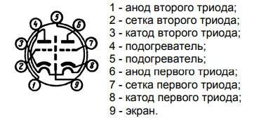
To understand the correct placement of the legs of the lamp (information for those who have not handled lamps before), you need to turn the legs towards you and the key downwards (the sector without legs), then the beautiful look that stands in front of you will be and paintings with pink lamps (This applies to most other lamps). As you can see from the little one, there are two lamps in the lamp, but we only need one. You can be vikorist anyway, it doesn’t make any difference.
Now we will show the diagram of the evil one to the right. Inductance coils L1 and L2 are best wound on a flat round base (frame), ideal for which a medical syringe with a diameter of 15 mm is suitable, and L1 should be wound over a cardboard tube, as it rolls around the body of the syringe with slight force , this will ensure the regulation of the connection between the coils. In the antenna core to the extreme L1 pin, you can solder a rod or solder a socket to the antenna and do something else more seriously.
L1 and L2 should be wound with a thick dart to improve the quality factor, for example, with a dart of 1 mm or more with a edge of 2 mm (special accuracy is not required here, so you don’t have to worry too much about the skin twist). For L1 you need to wind 2 turns, and for L2 - 4-5 turns.
Next come capacitors C1 and C2, which are a two-section variable-capacity capacitor (CPC) with a solid dielectric, which are ideal solutions for such circuits, CPC with a solid dielectric unfathomable. Of course, the KPI is the most basic element of this circuit, and it is easy to find in any old radio equipment or at flea markets, although it can be marked with two secondary capacitors (viscous ceramic), Then you will have to ensure adjustment with the help of an improvised variometer (addition for smooth change) of inductance). KPE butt:

We only need two sections of KPI and stench obov'yazkovo the butts are symmetrical, then. Mother, however, has the right regulation. The contact of the moving part of the KPI will be the exact one.
Then comes the quenching switch on resistor R1 (2.2 MΩ) and capacitor C3 (10 pF). Their values can be changed within small limits.
Coil L3 plays the role of an anode choke, then. The high frequency is not allowed to travel further. You can use some kind of choke (just not on a loose magnetic conductor) with an inductance of 100-200 μH, or it’s easier to wind a thin enamel-coated dart onto the body of a specified pressure resistor with 100-200 turns.
Capacitor C4 serves as a storage unit at the output of the receiver. Headphones or boosters can be connected anywhere. His vengefulness can change over great boundaries. Bazhano, so that C4 is either spitting or paper, or with ceramic in the same way.
Resistor R3 is a 33 kOhm primary potentiometer, which serves to regulate the anode voltage, which allows you to change the lamp mode. This is necessary for more precise adjustment of the mode to a specific radio station. You can replace it with a fixed resistor, but it doesn’t matter.
This is where the elements ended. You see, the scheme is very simple.
And now the drive is just a little bit busy with the installation of the prime mover.
The anode can be safely adjusted from 10V to 30V (more is possible, otherwise it is a little unsafe to connect low-impedance equipment). The noise there is very small and for food supply the power supply will need to be of any pressure with the necessary voltage, but it is important to ensure stabilization and a minimum of noise.
And also the obligatory washroom is the preparation of the frying lamp (in the picture with the different symbols as heaters), the fragments cannot be processed without any reason. Here more current is needed (300-400 mA), but the voltage is only 6.3V. If the voltage is variable 50Hz, the voltage is constant, so it can range from 5 to 7V, or rather the canonical 6.3V. I especially didn’t try vikorystuvat 5V on roasted, but swedish for everything everything is fine. Voltage is supplied to legs 4 and 5.
Now about the installation. The ideal is to arrange all the elements of the circuit in a metal casing with the ground connected to one point, otherwise it is possible to do so without the casing. Since the circuit operates in the UKH range, all connections in the high-frequency part of the circuit must be kept as short as possible to ensure greater stability and operational efficiency. Axle butt of the first prototype:

Everything worked out for such a montage. With a metal body, the chassis is a little more stable:

For such circuits, hanging mounting is ideal, since it provides good electrical characteristics and allows you to make amendments to circuits without much difficulty, so that the board is no longer so easy and neat to remove. I can’t call my installation neat.
Now it's time to get better.
After you have 100% completed the installation correctly, applied voltage and nothing swelled or burned - this means that the entire circuit works as long as the correct values of the elements are selected. And after all, you will feel noise in your headphones. If you do not add stations for all positions of the KPI, and you are sure that you receive communication stations on other devices, then try changing the number of turns of the L2 coil, this will change the resonance frequency of the circuit And you can spend it on the required range. І try turning the knob of the variable resistor - this may help. If nothing helps, you can experiment with the antenna. This is where the blessing ends.
At this stage, everything has already been basically said, and a more immediate description is presented, which can be supplemented with video clips that illustrate the tricks at various stages of development and demonstrate the power of its work.
Pure tube version (on the prototype level):
Option for adding ULF to the IMS (already with the chassis):
In the remaining version, the lamp power is wasted, since the IMC is sealed. This turned out to be the same solution, because with the anode 20V in the ULF mode, the other triode was not obtained from me, although I might need the required mode, otherwise I could not find out.
As a VLF, there is a victorious booster PAM8403, which is based on a linear voltage stabilizer L7805 (popularly called a crank, after the name of the Radian analogue).
The plans for the development of this project include the creation of another supergenerator on a 6s6b lamp, but also a portable one, just like the mother’s portable portable device.
I thank you for your respect. Ready to respond to questions on the topic.
PS: This device generates noise during operation and transmits it through the main antenna. The regenerator can be opened pereshkodi, vrahovite tse.
Dzherela:
1. Overregeneration
2. Supraregenerative primer
3. Documentation for the 6n23p lamp
4. Tutorsky “The simplest amateur transmissions and receptions of UKH” 1952
On the pages of our site, the topic of sound has been raised many times, and for those who want to continue their knowledge of radio tubes, we have prepared a circuit for receiving the HF range. This radio receiver is very sensitive and selective for receiving short-wave frequencies throughout the world. One half lamp 6AN8 serve as an RF booster, and also as a regenerative agent. A prime use for working with headphones or as a tuner with the next step we will call the bass booster.
For the body, use heavy-duty aluminum. The scales are placed on the arches of thick glossy paper and then glued to the front panel. The coil data is shown on the diagram, and the frame diameter is also there. The thickness of the dart is 0.3-0.5 mm. Winding turn to turn.


For the radio power supply unit, you will need to know a standard transformer, such as a low-power tube radio, that will provide approximately 180 volts of anode voltage at a current of 50 mA and 6.3 V voltage. It is not difficult to work straightening from the middle point - to grind the original pavement. Voltage allowance is permissible within +-15%.

Adjustment and elimination of malfunctions
Tune to the following station using the additional replacement capacitor C5 approx. Now capacitor C6 is for precise adjustment to the station. If your receiver will not normally receive, or change the values of resistors R5 and R7, which will form an additional voltage through the potentiometer R6 on the 7th output lamp, or simply swap the connections of contacts 3 and 4 on the return coil connection L2. The minimum antenna depth will be approximately 3 meters. It will be difficult to accept the original telescopic one.
The topic of retro devices, or regenerative ones, is constantly and rapidly developing on many sites and has already become popular with me. As a result, the idea arose to create a simple, or high-range, single-lamp regenerator, which could later be transformed into a complex, or high-range, superheterodyne, with a minimum of scarce parts.
Let me introduce to your respects a very simple and miraculously working circuit on HF of a single-tube regenerative receiver on a 6N2P sub-triode. 
Principle diagram induced in Fig. 1. I have tried a number of variants of simple single-lamp regenerators and the presentations here, in my opinion, are the best for the variety of criteria and yearly repetition.
The basis of the boule is taken from the wonderfully simple and sophisticated design of V. Yegorov “A simple short-haired trick” (Radio, 1950, No. 3). After testing this method, the scheme was slightly updated
- introduced environmental protection in the other cascade and strengthened in the first one (in the regenerator). This became possible due to the specific features of the triodes - obviously high penetration, or, because of the rapid influx of anode pressure on the grid-cathode, the anode resistors of the large support create a large “internal” OS equivalent to the support introduced into the cathode = Ra/u, in Our voltage is 47kOhm/100=470 Ohm, which will ensure high stability of the current mode. Another “function” of the cathode subtraction in the ULF is to displace the operating point on the linear distance of the current-voltage characteristic so that there is no interference - this is also relevant, because In our regenerator, the signal to the ULF input is very small (no more than tens of mV).
- High voltage has been removed from the headphones (as if you are motorically aware that 200V is being supplied to the head).
— The transition and blocking capacities are now adjusted to the functions of single-lank low-pass filters and low-pass filters and high-pass filters so as to ensure a smooth signal of approximately 300-3000 Hz.
- The two-part attenuator allows not only to ensure the normal operation of the robot, incl. full-sized antenna, and also ensuring a very soft approach to regeneration (in the original it was harsh, which did not allow for high sensitivity).
As a result, there is high stability (at twenty times I hear an SSB station every day/year, and at eighty, I have been hearing a group of stations for more than 5 years without any adjustment!) and sensitivity (about tens of μV - how to figure it out more precisely without inventing it - hi !), excellent repeatability (although the feedback of this parameter is small due to the variation in the characteristics of the lamps) and very simple controls - with a large frequency difference, or after switching the ranges, I set the attenuator to the middle position, using potentiometer R3 start generation (easy clicking on phones) And that’s all, then use two knobs - the adjustable knobs (KPI) and the attenuator - when indicated on the diagram, it is turned on, in fact, a universal regulator - simultaneously regulates the attenuation and generation threshold.
Features of the design visible in the photo. 
 As a shielded case, the same case is made from an old computer power supply. Obviously, a lamp had been transferred to another lamp on the chassis. The roasted food has been stabilized. Headphones are electromagnetic, high-impedance (with coils of electromagnets with an inductance of approximately 0.5 H and a support for a constant current of 1500 ... 2200 Ohm), for example, type TON-1, TON-2, TON-2m, 4, TA- 56m. It is better to freeze the KPI with a damaged electrical insulator. It is important to change the capacitance and inductance of your coil to find the necessary ranges of capacitor sizes that you may have to override using another simple program. KONTUR3C_ver. by US5MSQ
. To turn off the balling and cracking of the offending sections of the gearbox, they are turned on sequentially, and the rotor together with the gearbox body is insulated from the chassis (a similar differential gearbox). For not very high frequencies, you don’t have to worry about isolating the KPI, but, in fact, you can’t just make money - I spent money on making a bracket with getinaks - without a lot of smoke breaks (hi!).
As a shielded case, the same case is made from an old computer power supply. Obviously, a lamp had been transferred to another lamp on the chassis. The roasted food has been stabilized. Headphones are electromagnetic, high-impedance (with coils of electromagnets with an inductance of approximately 0.5 H and a support for a constant current of 1500 ... 2200 Ohm), for example, type TON-1, TON-2, TON-2m, 4, TA- 56m. It is better to freeze the KPI with a damaged electrical insulator. It is important to change the capacitance and inductance of your coil to find the necessary ranges of capacitor sizes that you may have to override using another simple program. KONTUR3C_ver. by US5MSQ
. To turn off the balling and cracking of the offending sections of the gearbox, they are turned on sequentially, and the rotor together with the gearbox body is insulated from the chassis (a similar differential gearbox). For not very high frequencies, you don’t have to worry about isolating the KPI, but, in fact, you can’t just make money - I spent money on making a bracket with getinaks - without a lot of smoke breaks (hi!).  Regardless of the fact that, in principle, the regenerator can be used (in order to regenerate the circuit) practically with any coil, it is important that the inductance coil is as low as possible, the design quality factor is as low as possible - so that with the same results, less inclusion of the lamp in the circuit is possible, , obviously , reduce their destabilizing influx (both themselves and the power supply circuits mediated through them). It is best to wind the coil on frames with a large diameter or, even better, on Amidon rings (for example, T50-6, T50-2, T68-6, T68-2 etc.).
The number of turns for selecting the designated inductance can be determined by any program, for example, for primary frames there is a manual program COIL 32
, and for the ring Amidon mini Ring Core Calculator
. The number of turns of the contour coil can be taken from 1/5...1/8 (for basic frames) to 1/10...1/20 (for Amidon).
Replace the lamp quickly. This circuit has a high gain coefficient “mu”, but the flow rate of 6N2P is also acceptable - you can install an effective RC filter along the anode life without bulky chokes or electronic filters bilizers - it’s the same way I have no background in the headphones. Therefore, the best replacement would be 6N9S. At the same time, it is possible to install any secondary triodes (6P1P, 6N3P, etc.) without adjusting the circuit and even without harm (there will be a little less (2 times) increase in the low frequencies). On the other hand, with a larger anode flow and coolness of the lamps, you can replace high-impedance headphones with an output transformer and use more accessible low-impedance headphones with great sensitivity.
About the life of the regenerator. Power supply - and it is necessary to stabilize the life voltage (on the filament and anode) of the lamp regenerator often occurs on different forms and the results on this are often given super-sensitively - as there is no need to stabilize and straighten ( And having said this, everything works miraculously) until the obligatory stagnation is complete autonomous battery.
And as it is not surprising, if the definitions of both these and others are fair (!), it is important not to remember the main criteria (or, of course, possible), which hang up to the regenerator and those and other authors. Since the main thing is the simplicity of the design, why bother with stabilizing the food? Regenerators of the 20-50s (and hundreds (!) of different designs), based on this principle, worked miraculously and provided a completely decent reception, especially on radio bands. However, we only place sensitivity in the main place, and it apparently reaches its maximum at the generation threshold - the edge of the unstable point at which numerous external changes in parameters are introduced, and the increase in life stress none of the best ones, then the answer is obvious: if you want to lose your high results - life stresses need to be stabilized.
Circuit of a simple two-lump superheterodyne induced in Fig. 2. This is a multi-band device, and at 80 m VIN of direct power (the VL1.2 pentode acts as a decoupling UHF). On others, there is a superheterodyne with a quartz local oscillator and a variable frequency converter. Heterodyne, connected to triode VL1.1 and stabilized by one non-deficient quartz 10.7 MHz, operates on 40m and 20m on the main harmonic quartz, and on the 10th range the third harmonic 32.1 MHz. The scale is mechanical with a width of 500 kHz on the ranges 80 and 20 m - straight, and 40 and 10 - reversible (similar to the one in UW3DI). To ensure that the frequency range is assigned to the circuit, the frequency range of the regenerative receiver, which in this case plays a role in the IF path, the regenerative detector and the ULF, picks up 3.3-3.8 MHz.
When received in telegraph (autodyne) mode, sensitivity (at noise level = 10 dB) was approximately 1 μV (10 m), 0.7 (20 and 40 m) and 3 μV (80 m).
The PDF of the Dvobom -Development for the Assigned Scheme (Vsogo in Kotushki Bucks) V.O., The maximum of the maximum sensation of 10 m, and by 80m - PIDVISHENE of ZGASANNE, Chim Zhima, I. The Defmirnost of the General Diapasoni. This cat is placed in the same place on the important diagram. The installation is hanging, you can clearly see it in the photo. Vimogos up to the new standard - maximum fastening and minimum voltage of RF conductors. 

Setting up can be simpler and more standard. After checking the correctness of installation and steady state modes, the stream is switched to the 80m range and the regenerative receiver is adjusted according to the above-described method. To set the frequency range, the GSS is connected through a partition directly to the grid (connector 2) VL1.2. Then adjusting the PDF to the 80m band, for which the GSS is switched to the antenna input, set to a new middle frequency in the range of 3.65 MHz. We switch the regenerator to the generation mode (autodyne mode) and to the KPI, the GSS signal is detected. Heart cats feed PDF to the maximum signal. At this point, the adjustment of the 80m band is completed and the coil cores can no longer be cleaned. Next we check the local oscillator. By connecting to the cathode (voltage 7) VL1.2 to control the voltage level of the local oscillator, a tube voltmeter can be used (as there is no power supply, you can use the simplest voltage probe, similar to the descriptions in) or an oscilloscope with a transmittance of at least 30 M Hz with a low frequency (high, at As an extreme option, connect it through a small (3-5 pF) capacitance.
By switching to the 40 and 20m ranges, we check the presence of alternating voltage in the order of 1-2 Veff. Then the 10m range is switched on and adjustments C1 achieve the maximum generation voltage - it may be approximately the same level.
Then we continue adjusting the PDF, starting with the 10m band, and finally reconnect the GSS to the antenna input, setting the new middle frequency to the range of 28.55 MHz. We switch the regenerator to the generation mode (autodyne mode) and to the KPI, the GSS signal is detected. And trimmers C8, C19 (coil cores cannot be touched!) adjust the PDF to the maximum signal. Similarly, the adjusted ranges are 20 and 40 m, for which the average frequencies of the ranges will be 14.175 and 7.1 MHz, and the trimmers will be C7, C15 and C6, C13.
For the purpose of the power supply, the device can be equipped with a pressure booster, following standard circuits on lamps 6P14P, 6F3P. 6F5P. During the preparation of this technique, some of our colleagues showed a great mastery of attitude.
Good fortune and great acceptance of Vikonanny Pavel (nick name) Pasha Megavolt
) - Div. Photo. 
And to be found in the armchairs of the hand-woven dress of the viconanne LZ2XL,LZ3NF.
You will often be asked about connecting to any digital scale terminal. I wouldn’t introduce a digital scale there - first of all, the mechanical scale is simple, the calibration is more stable, it’s enough to carry it out on just one 80th range, and on the scale the markings are drawn with a simple shift behind the vibrating frequency of the stand generator. In another way, the digital scale itself, in the near future, may be a mismatch, then. It will be necessary to think carefully about the design and, obviously, to introduce a shield as a minimum of the regenerator coil (the sensitivity of this one is a few microvolts!), and possibly the scale itself.
If you still enter it, then earn it the best way
- local oscillator through the stock repeater on KP303 (KP302,307 or imported BF245, J310, etc.) with a gate through a 1 kohm resistor directly to pin 7 VL1
- The regenerator under PIC regulation can have very low voltage on the circuit (tens of mV), so the regenerator signal requires not only decoupling, but also strengthening. The best option is to use a gate valve type KP327 or import (BF9xx), connected behind a standard circuit (displacement on the 2nd gate generates +4V) and connected to a 1 kohm resistor in the drain. The first gate is connected through a resistor that opens, 1 kOhm, to pin 3 of VL2.
P.S. Through a number of rocks after preparing the distance from the distant police force, the blowing super, blowing and soaking - it’s so good that in two evenings of unobtrusive care on the skin from the lower ranges (8 0 and 40m) signals were received from all 10 areas of Kolishny SRSR.
The DD and the vessel selectivity are low, but in the first phase it is supported by a smooth attenuator, and the other by a little bit of sound transmission (regeneration knob), the most important thing is to switch to a less populated frequency (hi!), and this is not less likely to cause overpopulation. All ranges are available At a minimum, accept the basic information. But its main advantage (besides the simplicity of the design) is that the frequency stability is very good, you can listen to stations for years without adjustment, and with equal success not only in the lower, but even in the 10th range!
Having changed the sensitivity - at s/noise = 10 dB it corresponds to the induced signal, and if you connect to the output signal equal to 50 mV (already add a buzzing signal on the TON-2 headphones), but it turned out like this,