How to measure with an electronic tester (multimeter). Dt830b multimeter instructions for use DC voltage measurement
A multimeter is a very useful device that will allow both a beginner and an experienced electrician to quickly check the voltage in the network, the operability of the electrical device and even the current in the circuit. In fact, working with this type of tester is not at all difficult, the main thing is to remember the correct connection of the probes, as well as the purpose of all the ranges indicated on the front panel. Next, we will provide detailed instructions for dummies on how to use a multimeter at home!
Meet the tester
First of all, we will briefly tell you what is on the front panel of the measuring device and what functions you can use when working with the tester, after which we will tell you how to measure resistance, current and voltage in the network. So, on the front side of the digital multimeter there are the following designations:
- OFF - the tester is off;
- ACV - alternating voltage;
- DCV - constant voltage;
- DCA - direct current;
- Ω - resistance;
You can clearly see the front view of the electronic tester in the photo:
Probably, you immediately noticed the 3 connectors for connecting probes? So here you need to immediately warn you that it is necessary to correctly connect the tentacles to the tester before measurements. The black wire is always connected to the output marked COM. Red according to the situation: in order to check the voltage in the network, the current strength up to 200 mA or resistance - you must use the "VΩmA" output, if you need to measure the current value over 200 mA, be sure to insert the red probe into the socket marked "10 ADC". If you do not take this requirement into account and use the VΩmA connector to measure high currents, the multimeter will quickly fail because the fuse will blow!
There are also old-style instruments - analog or, as they are commonly called - pointer multimeters. The arrow model is practically not used anymore. such a scale has a higher error and, moreover, it is less convenient to measure voltage, resistance and current on a dial board. 
If you are interested in how to use a pointer multimeter at home, we immediately recommend watching a visual video lesson:
Learning to work with an analog model
How to use the more modern digital model of the tester, we will talk in more detail later, having considered the step-by-step instructions in the pictures.
We measure the voltage
To independently measure the voltage in the circuit, you must first move the switch to the desired position. In a network with alternating voltage (for example, in a socket), the switch arrow must be in the ACV position. The probes must be connected to the COM and VΩmA sockets. Next, select the approximate voltage range for the network. If at this stage there are difficulties, it is better to set the switch to the largest value - for example, 750 Volts. Further, if a lower voltage is displayed on the display, you can move the switch to a lower level: 200 or 50 Volts. Thus, by decreasing the setpoint to a more suitable one, you can determine the most accurate value. In a network with constant voltage, use a multimeter in the same way. Usually, in the latter case, the switch is best set at around 20 volts (for example, when repairing a car's electrical system).
A very important nuance that you should know about is that you need to connect the tentacles to the circuit in parallel, as shown in the picture: 
We measure the current
In order to independently measure the current in the circuit with a multimeter, you must first decide whether direct or alternating current flows through the wires. After that, you need to find out the approximate value in Amperes in order to select the appropriate jack for connecting the black probe - "VΩmA" or "10 A". We recommend that you initially insert the probe into the connector with a higher current value, and if the display shows a lower value, switch the plug to another socket. If, again, you see that the measured value is less than the set point, the range with the lower value in Amperes must be used. 
We draw your attention to the fact that if you decide to use a multimeter as an ammeter, you need to connect the tester to the circuit in series, as shown in the picture: 
Measuring resistance
Well, the safest thing in relation to the safety of the multimeter will be to use a device to measure the resistance of the circuit elements. In this case, you can set the switch to any range of the “Ω” sector, and then select a suitable setting for more accurate measurements. A very important point - before using the device to measure resistance, be sure to turn off the power in the circuit, even if it is an ordinary battery. Otherwise, your tester in ohmmeter mode may show an incorrect value. 
Most often, you have to measure the resistance with a multimeter with your own hands. For example, if, you can measure the resistance of a heating element that is most likely out of order.
By the way, if, when measuring the resistance in the circuit section with a multimeter, you see the value "1", "OL" or "OVER" on the display, then you need to move the switch to a higher range, because an overload occurs at the setting you selected. At the same time, if the dial shows "0", turn the tester to a smaller measuring range. Remember this moment and it will not be difficult to use a multimeter when measuring resistance!
We use dialing
If you take a closer look at the front panel of the tester, you can see a few more additional features that we haven't covered yet. Some of them are used only by experienced radio technicians, so it makes no sense for a home electrician to talk about them (anyway, they are unlikely to be useful in domestic conditions). But there is one more important mode of the tester, which, perhaps, you will use - dialing (in the picture below we indicated its designation). For example, to find in a circuit, you need to ring the wiring, and if the circuit is closed, you will hear a sound indication. To do this, you just need to connect the probes to the desired 2 points of the circuit. 
Again, a very important nuance - the power on the section of the circuit that you are going to call must be disconnected. For example, if you decide
If you are wondering " How to use a multimeter?”, Then at least you already know what electric current and voltage are. If not, then I suggest you read the first chapters of my electronics textbook.
So what is a multimeter?
Multimeter - it is a universal combined measuring device that combines the functions of several measuring devices, that is, it can measure a whole range of electrical quantities.
The smallest set of functions of the multimeter is the measurement of voltage, current and resistance. However, modern manufacturers do not stop at this, but add to the set of functions, such as measuring the capacitance of capacitors, current frequency, diode continuity (measuring the voltage drop at the pn junction), sound probe, temperature measurement, measuring some parameters of transistors, built-in low-frequency generator, and much more. With such a set of functions of a modern multimeter, the question really arises of how to use it?
In addition, multimeters are digital and analog ... We will not delve into the jungle, I will only say that they outwardly differ in instruments for displaying measured values. In an analog multimeter, it is a pointer, in a digital one in the form of a seven-segment indicator. However, we are used to understanding the word multimeter as a digital multimeter. Therefore, in this article I will tell you exactly how to use a digital multimeter.
For example, take the widely used multimeters of the series M-830 or DT-830... There are several modifications in this series, their marking is distinguished by the last digit, as well as by the set of functions incorporated in this device.
I plan to review the multimeters of this line in one of the next issues of the magazine, so do not forget to subscribe to new issues of the magazine at the end of the article. I will describe how to work with a multimeter using an example device M-831.
The main functions of the M-831 digital multimeter and the purpose of the device controls
Let's take a closer look at the external panel of the multimeter. Here we see in the upper part a seven-segment liquid crystal indicator, on which the measured values \u200b\u200bwill be displayed.

Let's take a closer look at all the designations that are applied in a circle, thereby analyzing the operating modes of the multimeter.

1- turn off the multimeter.
2 - mode for measuring AC voltage values, has two measurement ranges of 200 and 600 volts.
ACV - AC Voltage - (eng. Alternating Current Voltage) - AC voltage
3 -mode for measuring DC values \u200b\u200bin the following ranges: 200 μA, 2000 μA, 20 mA, 200 mA.
Other models of multimeters may use the designation DCA - (eng. Direct Current Amperage) - direct current.
4 -mode for measuring large values \u200b\u200bof direct current up to 10 amperes.
5 - audible continuity of wires, the audible signal turns on when the resistance of the ringed section is less than 50 ohms.
6 - checking the health of the diodes, shows the voltage drop at the p-n junction of the diode.
7 - resistance measurement mode, has five ranges: 200 Ohm, 2000 Ohm, 20 kOhm, 200 kOhm, 2000 kOhm.
8 - DC voltage measurement mode, has five ranges of 200 mV, 2000 mV, 20 V, 200 V and 600 V.
Other models of multimeters may use the designation DCV - DC Voltage - (eng. Direct Current Voltage) - constant pressure.
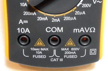
In the lower right corner of the front panel of the multimeter there are three sockets for connecting the supplied cords with probes.

Everything is simple here:
Bottom socket for common (negative) wire in all modes and on all ranges;
Medium socket for positive lead in all modes and on all ranges except for current measurement mode up to 10 A;
Upper positive terminal for current measurement up to 10 A.
Be careful, when measuring a current greater than 200 mA, connect the positive wire only to the upper socket!
The multimeter is powered by a 9-volt "Krona" type battery or, according to the standard size - 6F22.

Inside, under the back cover of the multimeter, there is a fuse, usually 250 mA, which protects the device in current measurement mode up to 200 mA.

Measuring electrical quantities with a multimeter
So now is the time to learn how to use your multimeter. We will learn to measure electrical quantities using the example of the same M-831 multimeter. Let me remind you once again that using this multimeter you can measure direct and alternating voltage up to 600 volts, only direct current values \u200b\u200bup to 10 amperes and electrical (active) resistance values \u200b\u200bup to 2 megohms.
Let me remind you that to measure the voltage on an element (section) of an electrical circuit, the device is connected in parallel to this element (or section of the circuit).
To measure the current in the circuit, the device is connected to the open circuit of the measured circuit (that is, in series with the circuit elements).

How to use a multimeter when measuring DC voltage.
Now let me tell you in detail, step by step, how to measure a constant voltage with our multimeter.
The first thing to do is to select the type of voltage to be measured and the measurement limit. For DC voltage measurement, the multimeter has a full DC voltage range, which are set using the limit switch.
To set the measurement limit, we first determine approximately what voltage value we want to measure. Here you need to act according to the situation, if you measure the voltage of the power supply elements (batteries, accumulators), then look for the inscriptions on the elements, if you measure the voltage in various electrical circuits, then I think since you have already "climbed" there, then you already know how use a multimeter!
Let's say we need to measure the constant voltage on the battery from some kind of electronic device (I'll take the video camera battery).
1. We study carefully the inscriptions on the battery, we see that the battery voltage is 7.4 volts.

2. We set the measurement limit more than this voltage, but preferably close to this value, then the measurements will be more accurate.

For our example, the measurement limit is 20 volts.
Nevertheless, when measuring voltage, for example, in circuits, I advise you to set a limit higher than the supply voltage of the circuit, so as not to cause the device to fail.
3. We connect the multimeter to the battery terminals (or parallel to the section where you are measuring the voltage).
A black probe, one end to the COM jack of the multimeter, the other to the minus of the voltage source being measured;
The red test lead to the VΩmA jack and to the plus of the measured voltage source.

4. Remove the DC voltage value from the LCD indicator.
Note: if you do not know the approximate value of the measured voltage value, then the measurement must be started by setting the largest limit, that is, for the M-831 - 600 volts, and consistently approaching the limit closest to the measured voltage value.
How to use a multimeter when measuring AC voltage.
Measuring AC voltage follows the same principle as measuring DC voltage.
Switch the instrument to AC voltage measurement by selecting the appropriate AC voltage measurement range.

How to use a multimeter when measuring DC current.
Let me remind you that the 830 series instruments measure only DC values, so if you need to measure the current in the AC circuit, then look for another device.
A multimeter for measuring current is connected to the open circuit of the measured circuit.

Again, it is necessary to determine the maximum possible value of the current in the measured circuit.
If the current values \u200b\u200bare less than 200 mA, then we select the appropriate measurement limit, connect the red probe to the socket VΩmA and turn on the multimeter to open the circuit.

To measure current in the range 200mA-10A, connect the red probe to the socket 10A .

It is advisable to connect a multimeter in the current measurement mode to the circuit with the voltage removed in the circuit, and at the limit of 10A this is a mandatory operation, since at high currents it is not at all safe.
And the last nuance: in the characteristics of devices from some manufacturers, it is not recommended to turn on a multimeter to measure current at a limit of 10 A for more than 15 seconds.
How to use a multimeter when measuring resistance.
To measure resistance with a multimeter, the latter must be switched to one of five resistance measurement limits.
Moreover, the rules for choosing the measurement limit are as follows:
1. If you know in advance the value of the measured resistance (for example, in the case of checking the resistor for "good" or "faulty"), then the measurement limit is selected more than the value of the measured resistance, but as close to it as possible. Only in this case will you minimize the error in measuring resistance.
2. If you do not know in advance the value of the measured resistance, then you need to set the maximum measurement limit (for M-831 it is 2000 kOhm) and changing the limits to consistently approach the measured resistance value.
Note: if "1" is displayed on the multimeter screen, then the value of the measured resistance is greater than the set measurement limit, in this case it is necessary to switch the limit towards its increase.
To measure resistance, simply connect the test leads of the device to the element whose resistance you want to measure and take readings from the indicator of the device.

Watch this video and learn not only how to measure current, voltage and resistance, but also how to ring the wires and check the health of diodes with a multimeter!
The home craftsman periodically needs to measure the parameters of the circuits. Check what voltage is currently in the network, whether the cable is frayed, etc. For these purposes, there are small devices - multimeters. With their small size and cost, they allow you to measure various electrical parameters. We will talk about how to use a multimeter further.
External structure and function
Recently, specialists and radio amateurs mainly use electronic models of multimeters. This does not mean that the turnouts are not used at all. They are irreplaceable when, due to strong interference, electronic ones simply do not work. But in most cases, we are dealing with digital models.
There are different modifications of these measuring devices with different measurement accuracy, different functionality. There are automatic multimeters in which the switch has only a few positions - they choose the nature of the measurement (voltage, resistance, current) and the device chooses the measurement limits itself. There are models that can be connected to a computer. They transfer the measurement data directly to a computer, where they can be saved.
But most do-it-yourselfers use inexpensive, mid-range models (with 3.5 bit depth, which provides 1% accuracy). These are common dt multimeters 830, 831, 832, 833.834, etc. The last figure shows the "freshness" of the modification. Later models have wider functionality, but for home use these new features are not critical. Working with all these models is not much different, so we will talk in general about techniques and procedures.
The structure of an electronic multimeter
Before using the multimeter, let's study its structure. Electronic models have a small LCD screen on which the measurement results are displayed. There is a range switch below the screen. It rotates on its own axis. The part with a red dot or arrow indicates the current type and range of measurements. Around the switch, there are marks by which the type of measurements and their range are set.

Below on the body there are sockets for connecting probes. There are two or three sockets depending on the model, there are always two probes. One is positive (red), the other negative is black. The black test lead always connects to the connector labeled "COM" or COMMON or labeled "ground". Red - to one of the free slots. If there are always two connectors, there are no problems, if there are three sockets, you need to read in the instructions for what measurements to insert the "plus" probe into which socket. In most cases, the red test lead is plugged into the middle socket. This is how most measurements are taken. The upper connector is necessary if the current is up to 10 A to measure (if more, then also to the middle slot).

There are models of testers in which the sockets are located not on the right, but below (for example, the Resant DT 181 multimeter or Hama 00081700 EM393 in the photo). There is no difference when connecting in this case: black for the socket with the inscription "COM", and red according to the situation - when measuring currents up to 200 mA to 10 A - in the far right socket, in all other situations - in the middle one.

There are models with four connectors. In this case, two sockets for measuring current - one for microcurrents (less than 200 mA), the second for a current from 200 mA to 10 A. Having understood what and why is in the device, you can begin to figure out how to use a multimeter.
Switch position
The measurement mode depends on which position the switch is in. There is a dot at one of its ends; it is usually tinted with white or red. This end indicates the current mode of operation. In some models, the switch is made in the form of a truncated cone or has one pointed edge. This sharp edge is also a pointer. To make it easier to work, you can apply bright paint to this pointing edge. It could be nail polish or some kind of abrasion resistant paint.

By turning this switch you change the operating mode of the device. If it stands straight up, the device is turned off. In addition, there are the following provisions:
- V with a wavy line or ACV (to the right of the "off" position) - AC voltage measurement mode;
- A with a straight line - DC current measurement;
- A with a wavy line - determination of alternating current (this mode is not available on all multimeters, in the above photos it is not);
- V with a straight line or the inscription DCV (to the left of the off position) - for measuring DC voltage;
- Ω - resistance measurement.
There are also provisions for determining the gain of transistors and determining the polarity of diodes. There may be others, but their purpose should be sought in the instructions for a specific device.
Measurements
The use of an electronic tester is convenient because you do not need to look for the desired scale, count the divisions, determining the readings. They will be displayed on the screen with an accuracy of two decimal places. If the measured value has polarity, the minus sign will also be displayed. If there is no minus, the measurement is positive.
How to measure resistance with a multimeter
To measure resistance, move the switch to the zone marked with the letter Ω. We choose any of the ranges. We apply one probe to one input, the second to the other. Those numbers that will appear on the display are the resistance of the element you are measuring.

Sometimes the screen does not display numbers. If "jumped out" 0, then it is necessary to change the measurement range to a smaller one. If the words "ol" or "over" are highlighted, there is a "1", the range is too small and should be increased. That's all the tricks for measuring resistance with a multimeter.
How to measure amperage
To select the measurement mode, you must first determine the DC or AC current. There may be problems with measuring AC parameters - this mode is not available on all models. But the procedure is the same regardless of the type of current - only the position of the switch changes.
D.C
So, having decided on the type of current, set the switch. Next, you need to decide which socket to connect the red probe to. If you do not even know approximately what values \u200b\u200byou should expect, so as not to accidentally burn the device, it is better to first install the probe in the upper (leftmost in other models) socket, which is labeled "10 A". If the reading is small - less than 200 mA, move the probe to the middle position.
The situation is exactly the same with the choice of the measurement range: first, set the maximum range, if it turns out to be too large, switch to the next smaller one. So until you see the readings.

To measure the current strength, the device must be included in the open circuit. The connection diagram is given in the figure. In this case, it is important to set the red probe to the "+" of the power source and touch the next circuit element with the black one. Do not forget when measuring that there is food, work carefully. Do not touch the bare ends of the probe or circuitry.
Alternating current
You can try the AC current measurement mode on any load connected to the household power supply and thus determine the current consumption. Since in this mode the device must be included in the circuit break, difficulties may arise with this. You can, as in the photo below, make a special cord for measurements. At one end of the cord there is a plug, on the other - a socket, cut one of the wires, attach two WAGO connectors to the ends. They are good because they also allow you to clamp the probes. After the measuring circuit is assembled, we proceed to measurements.

Move the switch to the "alternating current" position, select the measurement limit. Please note that exceeding the limits can damage the instrument. In the best case, the fuse will burn out, in the worst case, the "filling" will be damaged. Therefore, we act according to the scheme proposed above: first we set the maximum limit, then we gradually reduce it. (do not forget about rearranging the probes in the sockets).

Everything is now ready. First, connect the load to the outlet. You can use a table lamp. We insert the plug into the network. Numbers appear on the screen. This will be the current consumed by the lamp. In the same way, you can measure the current consumption for any device.
Measuring voltage
The voltage can also be alternating or constant, respectively, we select the required position. The approach to choosing a range is the same: if you don't know what to expect, set the maximum, gradually switching to a smaller scale. Do not forget to check if the probes are correctly connected to the right sockets.
In this case, the measuring device is connected in parallel. For example, you can measure the voltage of a battery or a conventional battery. We set the switch to the position of the DC voltage measurement mode, since we know the expected value, select the appropriate scale. Next, we touch the battery on both sides with the probes. The numbers on the screen will be the voltage that this battery produces.

How to use a multimeter to measure AC voltage? Yes, exactly the same. Just choose the right measurement limit.
Continuity of wires with a multimeter
This operation allows you to check the integrity of the wires. On the scale, we find a dialing sign - a schematic image of the sound (look at the photo, but there is a double mode, or maybe only a dialing sign). This image was chosen because if the wire is intact, the device emits a sound.

We put the switch in the desired position, the probes are connected as usual - in the lower and middle jacks. We touch one probe to one edge of the conductor, the other to the other. If we hear a sound, the wire is intact. In general, as you can see, using a multimeter is not difficult. Everything is easy to remember.
This digital multimeter is not the first one on my farm. There were already two similar ones. But the trouble is, the Chinese digital multimeter does not live for a very long time. Either the wires are falling off, or the screen. This time, I decided to choose a multimeter in which the wires are in the case, since it is not always convenient to store the wires separately, especially in a car. After all, I use it mainly as a car multimeter, because sometimes it is useful to check the battery with a multimeter. or the "charging" will disappear, you will have to check the generator, diodes, take measurements with a multimeter in different circuits of the car. The only drawback that this digital multimeter has, which upset me a little, is the lack of a sound signal in the “dialing” mode. But since there were no other such mobile multimeters in the choice, I had to buy this particular multimeter, and the price, although higher than the cheapest Chinese one, was still not so high. Yes, and I do not use a digital multimeter as a tester very often, so the lack of a sound signal is not such a drawback. The multimeter did not stay with me that long, not more than a year. But in the harsh winter, I recklessly decided to use it in a severe frost. So the wires just broke like matches. In general, non-replaceable wires are sometimes a minus in the properties of the tsashka.
DT 831 * Digital Multimeter
Low battery indication
Overload protection
Digital LCD display
Battery used: 9v, krone, 6F22
Weight: 145 grams.


The multimeter is a combined universal measuring instrument that combines several different functions from a variety of instruments. This device is capable of measuring a range of electrical quantities.
The smallest set of functions of such a device is the measurement of current, voltage and resistance. But nowadays technologies are constantly being improved, and manufacturers are trying to create an ever more functional device. Thus, manufacturers add a lot to the set of functions, for example, measuring the frequency of the current, the capacitance of the capacitors, as well as the voltage drop at a certain junction, the temperature of some parameters of the transistors, and so on. This set of functions makes the modern multimeter not the easiest product to use. Therefore, questions may arise as to how they should be used.
There are two main types of multimers - digital and analog. They have some external differences in the devices for displaying measured values. In an analog-type device, it is a pointer, and in a digital one - an indicator. Almost everyone now associates a digital model with the word multimeter. Therefore, we will focus on using just such a device.
As an example, consider the common devices of the DT-830 or M-830 series. There are several different modifications with different markings and some functions.
Key functions of the M-831 multimeter and features of controls
On the external panel of the multimeter there is a seven-segment liquid crystal indicator, which displays the values \u200b\u200bmeasured on it. In the central part of the device there is a switch for measuring limits and values.
On the front of the device there are many different designations, including turning off the multimeter, measuring DC values, audible continuity of wires, checking the health of diodes, measuring resistance values, and much more.
In the lower right corner of the panel there are three jacks that are used to connect the cords with the probes included in the kit. The bottom jack is used for common on all bands and in all modes. The middle socket is used for the positive wire, and the upper one for the same wire, but in the current measurement mode, no more than ten amperes.
A nine-volt Krona battery is used as a battery for the multimeter. There is a special fuse under the back cover, the capacity of which is usually 250 mA. It protects the device in current measurement mode, the limits of which do not exceed 200 mA.
Measurement of electrical quantities
It is very important to understand how to use your multimeter correctly. As an example, we will use the M-831 model. It is worth recalling that with this device you can measure AC and DC voltage up to 600 volts.